
A part can look straightforward in CAD and still resist release from the mold. When a molded wall drags, scuffs, whitens, or bends during ejection, draft is one of the first design features to review—but it is not the only one. Texture, draw depth, shrinkage, surface condition, cooling, and ejector support all affect how the part separates from the steel.
Short answer: An injection molding draft angle is the taper provided along the mold’s direction of pull. It reduces sliding contact during release. There is no single angle that works for every feature: the required draft depends on material, depth, texture, geometry, and cosmetic or dimensional requirements. Set it by surface and validate it on the actual part.
In this article:
- Why draft changes release behavior
- Which surfaces need the closest review
- Read ejection marks as evidence
- Balance draft with part function
- A practical design-review checklist
- Frequently asked questions
Why draft changes release behavior
As a tool opens, the molded part must move away from the cavity or core without excessive friction. A slight taper makes the gap increase along the pull direction, reducing the length of surface that rubs against the mold. Without enough release clearance, shrinkage can grip the core, texture can mechanically hold the surface, and ejection force can leave visible or dimensional damage.
Draft is not a substitute for a sound parting line or ejection layout. A part can have nominal draft and still stick if the core is rough, the steel is damaged, the part is too hot, the ejectors push unevenly, or the geometry creates a local lock. Autodesk’s design-for-manufacturing guidance similarly frames draft relative to the direction in which the part is removed from the mold; the direction of pull must therefore be agreed before the angle is evaluated.
Which surfaces need the closest review
Start with surfaces parallel to the primary opening direction: deep side walls, ribs, bosses, pockets, shutoffs, and cosmetic faces. Then review any feature released by a slide or lifter in its own pull direction. A side action changes the local release path; it does not automatically remove the need for draft on the surfaces that slide along it.
Depth and surface finish matter. A shallow polished wall and a deep textured wall do not have the same contact conditions. Texture can increase mechanical engagement, so the texture supplier’s specifications and the actual draw depth should be part of the design review. Likewise, a sealing land, mating bore, or alignment feature may have a functional geometry that cannot be casually tapered. Those surfaces need a deliberate tolerance and shutoff strategy rather than a blanket rule.
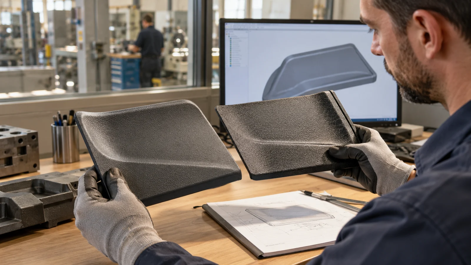
Material behavior also matters. Shrinkage can pull a part tightly around a core, while fillers and resin grade can influence friction, stiffness, and dimensional response. Use the supplier’s grade-specific processing information and confirm the tool’s intended steel condition; do not assume that a generic draft value applies equally to every polymer.
Read ejection marks as evidence
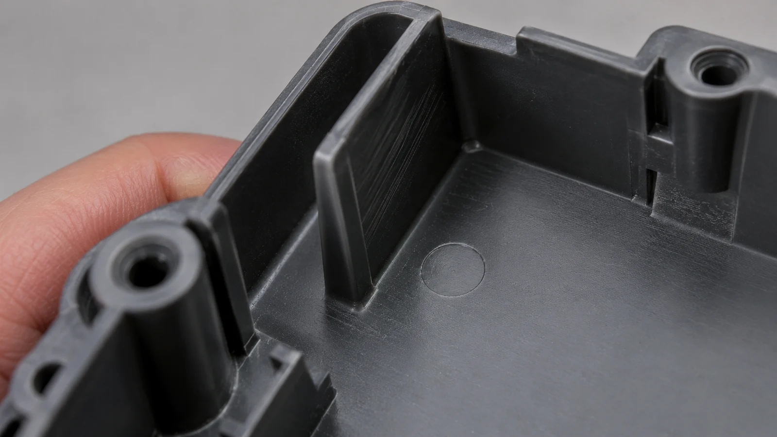
Different release defects point to different mechanisms. Broad scuffing on a wall can indicate excessive drag, insufficient draft, rough steel, or a surface that is being forced to slide. Whitening or stress marks near ejectors may indicate the part is still too hot, the ejection load is concentrated, or the feature is locally too flexible. A bent rib may be a support or ejection-position problem rather than simply an angle problem.
Map each mark to the tool side and the part’s pull direction. Check whether the problem repeats in every cavity, appears only after a process change, or tracks a specific core, insert, or texture area. That comparison helps separate a geometry issue from a local steel or process issue. If draft changes are being considered, review adjacent dimensions and fit; increasing taper can change opening size, wall profile, and the amount of material available at a mating feature.
Balance draft with part function
More draft can ease release, but it also changes geometry. It may alter a visible wall angle, reduce a feature’s usable depth, or affect how two parts align. Where a dimension must remain straight or parallel, consider whether the parting strategy, core layout, polish, texture, or local geometry can solve the release problem without changing the functional interface.
For a textured cosmetic wall, decide the finish and draft together. For a deep rib or pocket, consider whether the feature can be shortened, widened, or supported differently. For a dimension-critical surface, determine which area controls fit and where draft can be placed without compromising that function. These are appropriate topics for an early custom mold design review, before tool steel is committed.
Simulation and trial data can help resolve competing constraints. A mold flow analysis can inform filling, packing, and shrinkage questions, while physical sampling shows how the part releases from the finished steel. Keep the evidence distinct: simulation is not a substitute for a mold trial when the concern is actual release force or surface damage.
A practical design-review checklist
- Mark the pull directions. Identify the main opening direction and the separate directions for slides or lifters.
- Flag high-risk surfaces. Highlight deep draws, ribs, textured faces, shutoffs, and features with cosmetic or sealing requirements.
- State functional limits. Identify dimensions and interfaces that cannot change when draft is adjusted.
- Review resin and finish assumptions. Confirm the grade, expected shrinkage, and texture specification.
- Plan validation. During sampling, inspect release marks by cavity and tool side, then check dimensions after the part stabilizes.
When the tool is already built, avoid changing process settings and polishing steel at the same time. Record the baseline, test one controlled correction, and verify both release behavior and part dimensions. The mold trial and validation process should confirm the part—not merely that the mold completes a cycle.
Frequently asked questions
Is there a universal minimum draft angle for injection molding?
No universal value covers every resin, draw depth, texture, and geometry. Treat published rules of thumb as starting points for review, then confirm the actual surface and function with the tool and material team.
Can a part have zero draft?
Some local features may be designed with little or no draft when function requires it, but release becomes more sensitive to polish, geometry, shrinkage, ejection support, and process conditions. Review the risk explicitly rather than assuming the surface will release.
Will adding draft fix ejector marks?
Not always. Ejector marks can result from concentrated force, hot or flexible parts, incorrect ejector placement, or insufficient support. Draft should be checked alongside the ejection system and cooling state.
Does texture affect the draft requirement?
Yes. Texture can increase mechanical grip and change the release behavior. Confirm the specified texture with its supplier and evaluate it with the actual depth and pull direction.
Next step: Include the 3D model, resin grade, texture callouts, critical fit surfaces, and expected production volume in a moldability review so draft decisions are made against the complete part requirement.