
Cooling a multi-cavity mold is a cavity-to-cavity consistency problem as much as a cycle-time problem. The layout should remove heat from each repeated part without leaving one cavity systematically warmer, slower to release, or more prone to dimensional drift. Begin with the part’s thick sections and core geometry, then route circuits that are accessible, balanced, and practical to maintain.
Map heat before routing channels
Start from the molded part rather than a standard channel pattern. Mark thick sections, ribs, bosses, deep cores, and regions where the part must hold a critical dimension or appearance. These features can retain heat differently from nominal walls. The layout should address those local conditions while preserving adequate steel around cavities and other tool details.
For a multi-cavity tool, repeat this review for every cavity position. Identical parts do not guarantee identical cooling if channel lengths, connections, or surrounding steel differ across the mold. Document which cavity each cooling circuit serves so trial observations can be connected to the design.
Build circuits around cavity geometry
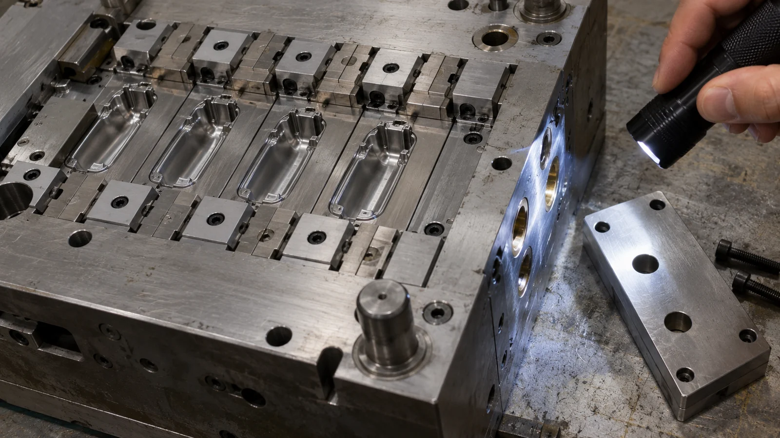
Cooling channels need to approach the molded surface closely enough to remove heat effectively, while maintaining tool strength and avoiding interference with gates, ejectors, slides, and fasteners. Deep cores or narrow features may require a different cooling detail from an open flat area. Baffles, bubblers, or other inserts may be considered where a straight drilled channel cannot reach the required region, but their suitability depends on the geometry and maintenance plan.
Think about circuit routing and flow path together. A circuit that passes several cavities in sequence can experience changing coolant conditions along its length; parallel circuits may simplify local control but require clear routing and connection management. Neither arrangement is universally better. The goal is to avoid a design where one cavity’s cooling depends unpredictably on another cavity’s heat load.
Keep serviceability visible in the design review. Connections should be identifiable, accessible, and protected against accidental damage. If circuits are difficult to flush, inspect, or reconnect, maintenance can gradually undermine the intended thermal balance.
Avoid cavity-to-cavity thermal imbalance
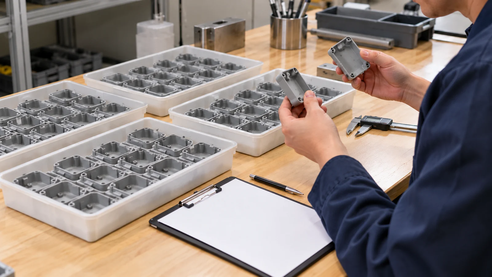
Uneven cooling can produce differences in shrinkage, warpage, release behavior, and cycle stability. When one cavity runs warmer, operators may be tempted to change common settings to fix its parts; that adjustment can shift the other cavities away from their own best conditions. The underlying issue may be circuit layout, flow restriction, blockage, or a part-specific geometry difference.
| Observed pattern | Cooling review |
|---|---|
| One cavity shows more warpage | Compare local heat concentration, cooling access, and part orientation. |
| One position releases later | Check core temperature, ejection loading, draft, and circuit condition. |
| Part dimensions vary by cavity | Relate measurements to cavity identity and compare thermal behavior. |
| Cycle changes shift defects between cavities | Review whether a shared setting is masking different cavity responses. |
This table is a diagnostic map, not a one-to-one cause list. Confirm the pattern with cavity-level samples and process observations before changing steel or operating conditions.
Verify the cooling design
Review the channel geometry in CAD and check that every circuit can be manufactured and inspected. During mold trials, record cavity identity when evaluating part dimensions, appearance, and release. Observe coolant connections and, where the process plan supports it, compare inlet and outlet conditions across circuits. Establish a baseline so later maintenance can identify a change rather than rely on memory.
Mold-flow or thermal analysis can help compare concepts early, but simulation depends on inputs and assumptions. It should guide questions about heat removal and flow, not replace tool trials and part measurement. The production window should be established from the actual resin, machine, mold, and acceptance criteria.
Design review questions
- Which part features retain heat or control critical dimensions?
- Does each cavity have an understandable, serviceable cooling path?
- Could one circuit’s changing load affect another cavity’s cooling?
- Can a technician identify, flush, and reconnect circuits without confusion?
- Will trial samples be traced by cavity so differences can be diagnosed?
For the broader multi-cavity mold design approach, cooling should be reviewed alongside runner balance, ejection, maintenance, and cavity-level inspection—not as a standalone channel drawing.
FAQ
Should all cavities use identical cooling circuits?
Not always. Matching cavity geometry may support similar circuits, but the final layout should reflect actual part features, tool construction, and maintainability. The objective is consistent part performance, not identical routing for its own sake.
Can colder coolant solve a cavity-to-cavity difference?
It may change the overall thermal condition but can leave the source of the imbalance unresolved. First compare cavity-level behavior and circuit condition before applying a common adjustment to every cavity.
How should cooling be checked during a trial?
Keep samples associated with cavity positions, record relevant process observations, and compare dimensions, warpage, appearance, and release behavior. Use the project’s quality plan to define measurement and sampling scope.