
High-speed injection molding defects often appear when faster filling exposes a limitation that was hidden at a slower rate: trapped air, an unstable flow front, shear-related appearance change, or a process window too narrow to hold. The fix is not automatically to slow the machine. First identify the defect’s location and timing, then determine whether the evidence points to fill speed, venting, gate design, material condition, or another process variable.
Start with where the defect appears
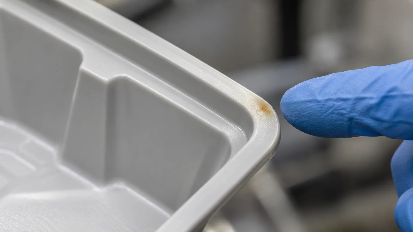
Map the defect on the part and note when it forms during filling. A mark at the end of fill may indicate a different issue from one that tracks a gate, a weld line, or a thin section. Compare acceptable and defective parts from the same cavity, and record whether the pattern repeats across cavities and cycles.
Also separate fill-stage symptoms from pack, cooling, and ejection effects. A defect observed after opening the mold may have formed earlier, but the timing of observation does not identify its cause. Process records and a controlled trial help connect appearance to the phase where the material or tool condition changed.
Match the symptom to the flow event
| Defect pattern | Questions to investigate |
|---|---|
| Burning or dark marks near the end of fill | Is air trapped at the flow front? Are vents clean and positioned for the actual fill pattern? |
| Jetting or a visible unstable flow line | Does the melt enter an open region without a controlled flow transition? Is the gate location appropriate? |
| Hesitation or incomplete thin sections | Does the flow slow at a thickness change or around a feature? Is the gate and pressure demand suitable? |
| Gloss or texture variation | Does the defect follow a cavity, a surface region, or a change in material and process history? |
| Flash after a speed increase | Did the pressure response, clamp condition, parting line, or tool condition change the result? |
These are starting questions, not one-to-one diagnoses. For example, burn marks can be associated with trapped air, but location and vent condition must be checked before changing speed or material settings. Likewise, a gloss change may reflect surface replication, material state, or process variation rather than speed alone.
Troubleshoot without losing the fast-fill target
- Preserve a baseline sample and document the current settings, material lot, and defect location.
- Review the fill pattern and determine whether the symptom is cavity-specific or shot-wide.
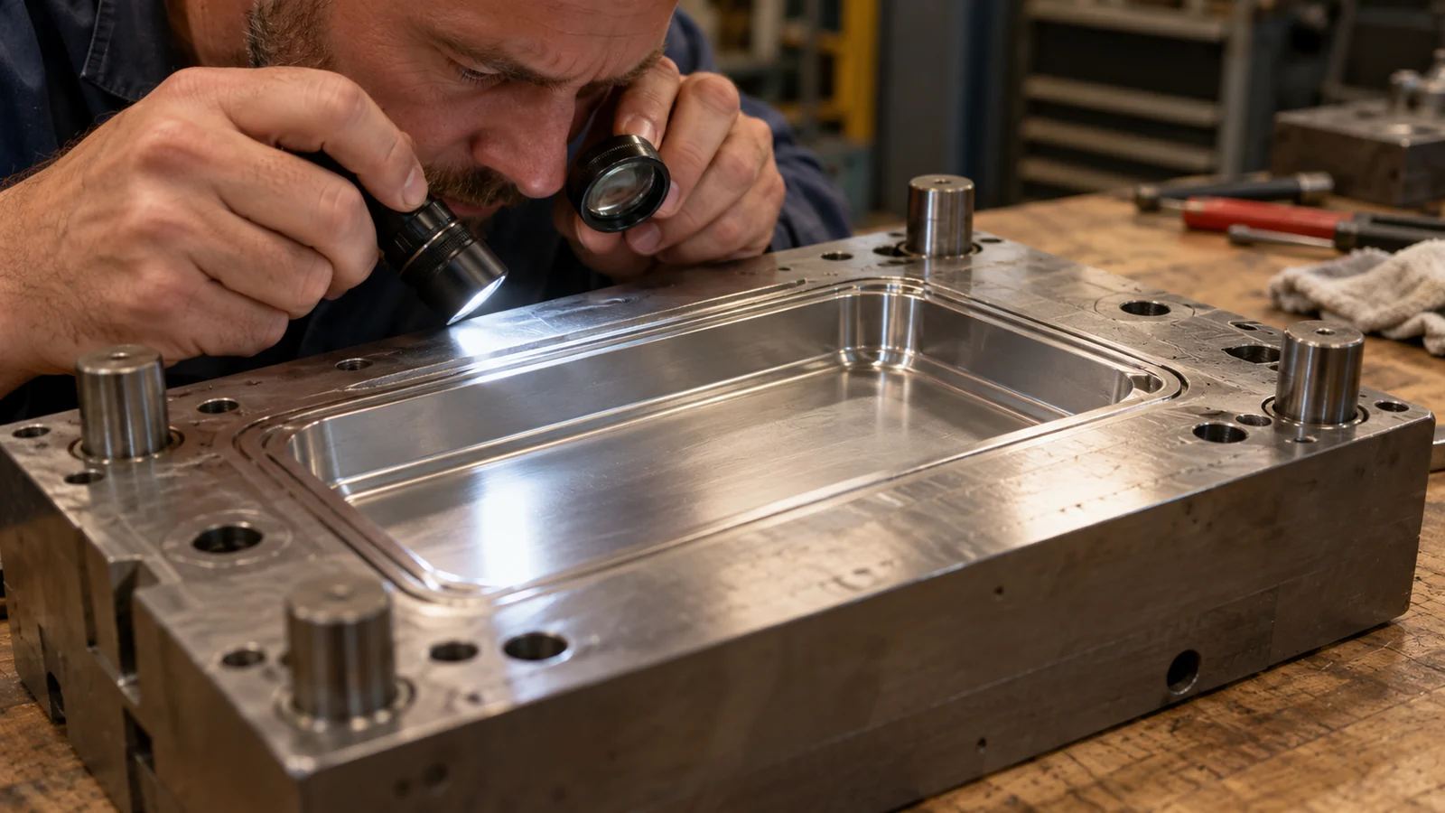
- Inspect vents, gate areas, and the parting line for contamination, wear, or blockage.
- Confirm resin identity, grade, drying and handling requirements, and recent material changes.
- Change one fill-related variable at a time and compare the full set of critical features.
- Check whether the correction improves all affected cavities without creating flash, weld-line, or dimensional issues elsewhere.
When the production objective requires a fast fill, a permanent reduction in speed may simply trade one defect for longer cycle time or incomplete filling. A better response may involve improving venting, reconsidering gate position, changing a flow transition, or widening the stable process window. Any tool change should be based on the actual part and validated samples.
When the design is limiting the process
If defects return whenever the process moves toward the intended fill rate, inspect the design and tool together. Thin walls, abrupt thickness changes, long flow lengths, restrictive gates, and difficult vent paths can narrow the usable window. Mold-flow analysis may help assess a proposed gate or wall change, but assumptions and material data should be checked against the real project.
Document the acceptable range and the conditions that create failure. The right process is not the fastest setting that produces a good sample once; it is a controlled range that can meet the part requirements on the intended tool and machine. For the broader production route, review high-volume injection molding in the context of the part’s process and quality needs.
FAQ
Should I lower injection speed whenever a burn mark appears?
Not without checking where the mark forms and whether air is trapped. Vent condition, flow-front behavior, gate location, and material history may be more relevant than a global speed reduction.
Can high fill speed cause flash?
It can contribute to a pressure response that reveals a weak or damaged parting-line condition, but flash can have multiple causes. Inspect the tool and compare the pattern before assigning the defect to speed alone.
How do I know whether the part design limits fast filling?
Look for repeated defects tied to thin sections, long flow paths, abrupt transitions, restrictive gates, or difficult vent locations. Use engineering analysis and controlled molding trials to verify a design change.