
Different plastic parts can share a family mold only when the mold can fill, pack, cool, and release each cavity without forcing one part’s requirements onto another. Matching resin is not enough. The first design review should compare each part’s projected area, wall sections, flow length, gate location, dimensional priorities, and expected production mix. If one component needs a substantially different process window or is molded in a different material, a family tool may create more balancing and quality risk than it removes.
Start with part compatibility, not part count
A family mold is a single tool containing cavities for two or more different components, commonly intended to produce a matched set in one molding cycle. The useful question is not simply whether the components belong to one assembly; it is whether they can be produced together under a stable, compatible process window.
Compare the parts in four groups before laying out cavities:
- Material: resin family, grade, color, reinforcement, drying needs, and any different melt or mold-temperature requirements.
- Flow: volume, wall-thickness transitions, flow length, gate options, and the pressure each cavity is likely to need.
- Quality: critical dimensions, appearance surfaces, weld-line limits, flash sensitivity, and inspection method.
- Production: demand ratio, packaging quantity, replacement-part demand, and whether all components are consumed at the same rate.
Several mismatches should stop the design review early. A small thin-wall cover paired with a thick structural bracket may not fill and pack well at the same conditions. A high-gloss cosmetic component may need a different venting and surface strategy from a hidden clip. Different resins can require incompatible processing conditions or may not be appropriate to run together in the same tool. These are not automatic disqualifiers, but they need a technical solution before steel is cut.
How a family mold is balanced
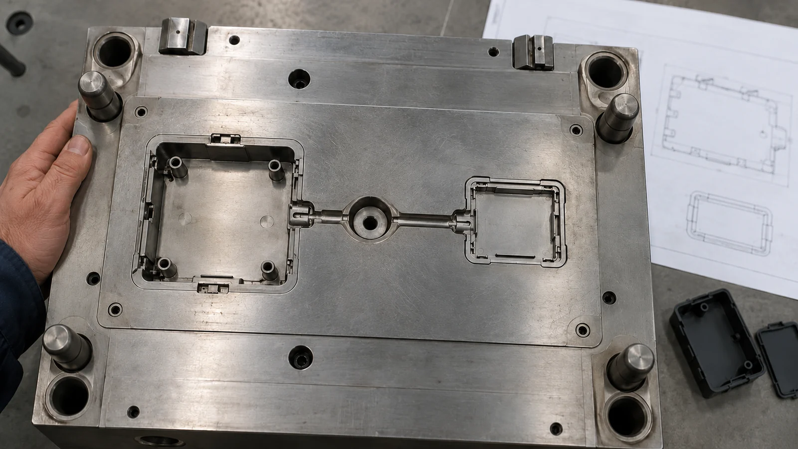
Each cavity must receive a suitable melt flow and packing history. In a naturally balanced runner layout, flow paths and restrictions are arranged so that melt reaches the cavities with comparable resistance. With unlike parts, equal runner length alone does not guarantee equal filling: cavity volume, gate size, wall thickness, and flow geometry also affect the result.
Start with the part geometry and likely gate locations, then assess whether a common runner system can feed all cavities without sacrificing the individual part requirements. A larger cavity may require a different gate area than a smaller one; a long, thin flow path may respond differently from a compact, thicker component. The goal is a usable process window across every part in the tool, not identical cavity pressure traces for their own sake.
Where the cavity loads differ substantially, the design may need independent flow restrictions, carefully positioned gates, or a more deliberate runner arrangement. Mold-flow analysis can help compare filling sequence, pressure demand, weld-line location, and temperature distribution before tooling decisions become expensive. Simulation is a design aid, not proof of a production-ready process: actual resin data, tool construction, machine capability, and molding trials still matter.
Cooling and ejection across different geometries
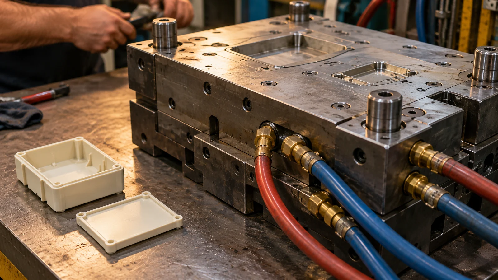
Different part shapes rarely remove heat at the same rate. A thick boss or rib junction can remain hot after a thin panel has stabilized, while an uneven cooling layout can cause different shrinkage, warpage, and cycle-time constraints among cavities. In a family tool, the slowest or least stable part can set the practical cycle for the entire shot.
Review cooling by local wall sections and heat concentration rather than by part outline alone. Give attention to thick-to-thin transitions, deep cores, bosses, and areas near gates. The layout must also leave room for robust cooling circuits and maintainable connections. If one part needs a much longer cooling period, ask whether that delay erases the shared-tool benefit or whether the design can be changed to improve heat removal.
Ejection deserves the same independent review. Each component needs enough draft and a predictable release path, even though the mold opens as one system. Different shrink behavior can make one part grip its core while another releases readily. Ejector placement should avoid cosmetic surfaces and functional datum areas, and the design should consider whether the parts can be removed and handled without damaging delicate features.
When shared tooling stops saving money
A family tool can reduce the number of separate molds and coordinate production of components that are regularly used together. But the cost comparison should include the complete operating route, not just the initial tool count.
| Cost or risk factor | Question for the design team |
|---|---|
| Demand mix | Are the parts consumed in similar quantities, or will one cavity create excess inventory? |
| Process window | Can every cavity meet its requirements at the same stable machine settings? |
| Tool maintenance | Will a repair or change to one cavity interrupt the production of all parts? |
| Quality control | Can each part be inspected and traced independently after a combined shot? |
| Future changes | Are the components likely to change at different times during product revisions? |
If one component’s demand is much lower, producing it in every shot may create work-in-process or obsolete inventory. If components change independently, a shared tool can make engineering changes and validation more complicated. A separate mold may cost more upfront but provide better scheduling, maintenance isolation, or process control over the product life.
A practical design review sequence
- Confirm the set: identify which parts are actually used together and compare forecast demand by component.
- Normalize the inputs: provide current CAD, resin and grade, appearance requirements, critical dimensions, and inspection criteria for every part.
- Compare process needs: assess wall sections, flow paths, likely gates, cooling time, shrinkage behavior, and release requirements.
- Test the common-window assumption: use engineering review and, where useful, mold-flow analysis to find whether the parts can share a stable process window.
- Compare full lifecycle routes: weigh one family tool against separate tools using production mix, maintenance, quality checks, and future revisions.
A family mold is a strong candidate when the components have compatible materials and molding needs, are consumed in a reasonably coordinated mix, and can be inspected without losing part-level control. For a broader look at how the tooling route is planned, review family injection mold solutions. If the parts need materially different process conditions, treat separate tooling as a legitimate baseline rather than a failure to optimize.
FAQ
Can different materials be molded in one family mold?
Sometimes, but it depends on the molding process and tool design. Materials with incompatible processing conditions or different shot requirements may make a conventional family mold impractical; confirm compatibility before selecting the tool concept.
Does every cavity need to produce the same part quantity?
A conventional family mold produces its cavity set in each cycle, so the parts are made in a fixed ratio. If usage or demand ratios differ, the resulting inventory may outweigh the benefit of a shared tool.
Is a family mold always cheaper than separate molds?
No. Tool count is only one cost component. Cycle constraints, balancing work, quality inspection, maintenance downtime, and mismatched demand can change the total-cost comparison.