
Achieving micron-level dimensional accuracy in multi-material plastic components presents extreme engineering challenges. Injecting two distinct polymer melts into a single mold tool requires managing rotational indexing alignment, differential resin shrinkage, and interfacial shut-off fitments concurrently. Cumulative tolerance stack-up errors between the first-shot substrate and second-shot cavity can cause severe parting line flash or crushed tool steel.
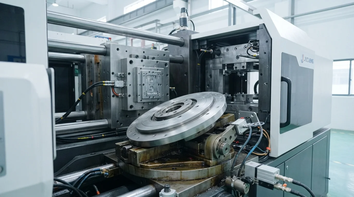
Understanding how machine turntable repeatability and thermal cooling dynamics influence part geometry enables product designers to establish realistic drawing specifications. This technical engineering guide examines rotary platen indexing precision, differential shrinkage compensation models, and advanced coordinate metrology protocols.
Mold Rotation Alignment Tolerances (±0.01 mm) and Cavity Indexing
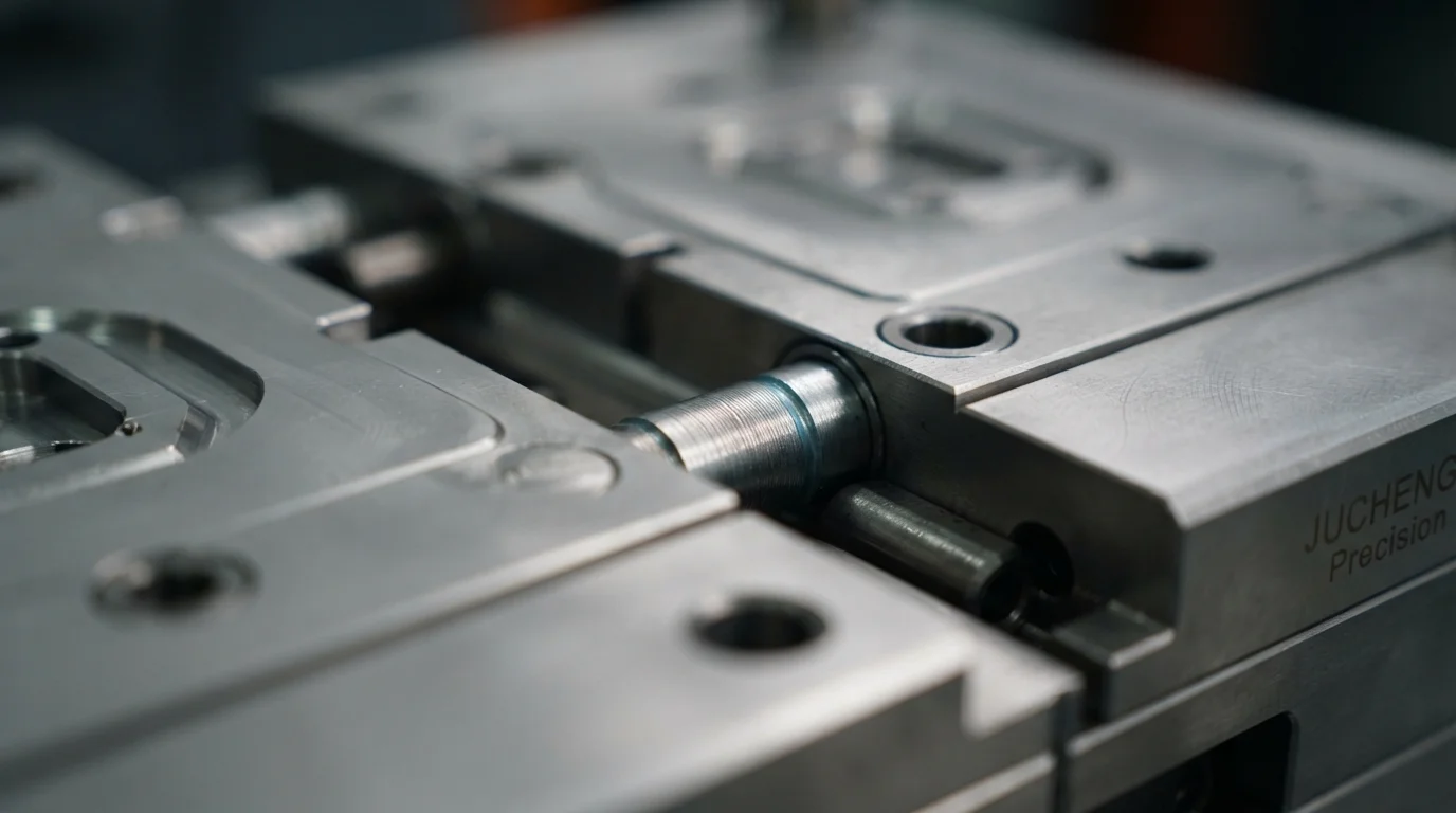
Maintaining tight two shot injection molding tolerances requires precise control over core platen rotation. Swiveling the mold core 180 degrees between injection stages relies on heavy-duty hydraulic or servo-electric rotary turntable platen mechanisms. Hardened mechanical locating pins and shot-pin interlocks engage alignment bushings on the stationary mold plate before clamp-up. Precision locating pin engagement guarantees that cavity-to-core indexing alignment remains strictly within ±0.01 mm over hundreds of thousands of cycles.
Maintaining sub-millimeter indexing repeatability prevents the secondary cavity steel from scuffing or crushing the pre-molded primary substrate. Tooling engineers grind shut-off lands with tight fitment tolerances to create sharp boundary seals between contrasting colors or materials.
Core alignment engineering protocols include:
- Rotary shot-pin engagement—Hydraulic shot pins lock the rotating platen mechanically before mold clamp-up pressure is applied.
- Cavity shut-off land fitting—Grinding tool steel sealing faces to fitment tolerances under ±0.01 mm prevents soft elastomer flash.
- Substrate clearance pocketing—Machining 0.15 mm relief steps on secondary cavity faces eliminates substrate crushing risks.
- Thermal channel synchronization—Balancing cooling circuit temperatures between stations 1 and 2 prevents asymmetrical core expansion.
Managing Differential Shrinkage Rates Between Two Different Resins
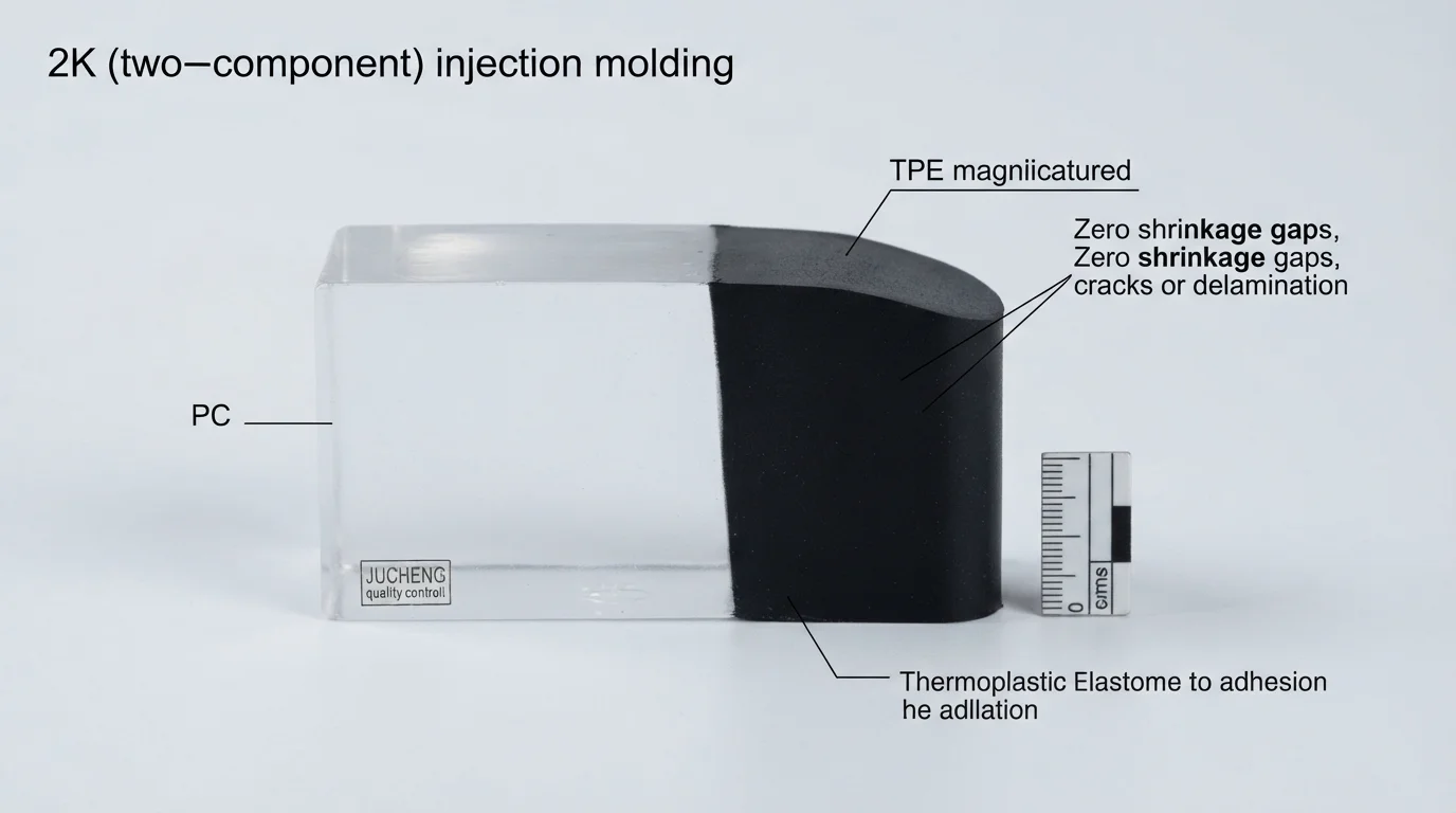
Managing differential shrinkage rates between contrasting polymers represents the most complex physical challenge in multi-shot engineering. Primary rigid substrates molded from amorphous resins like polycarbonate (PC) exhibit isotropic shrinkage rates of 0.5% to 0.7%. Secondary elastomeric layers of TPE or TPU contract at rates ranging from 1.2% to 2.5% during cooling. Semi-crystalline structural polymers like glass-filled PA66-GF30 shrink anisotropically depending on fiber orientation vectors.
Managing two shot injection molding tolerances across multi-resin components depends on pre-compensating tooling steel dimensions independently. Toolmakers calculate volumetric contraction differentials for each material stage, cutting core and cavity steel with custom pre-compensated dimensional offsets. Table 1 below outlines typical shrinkage differentials and achievable tolerance limits:
| Primary Substrate Resin | Substrate Shrinkage (%) | Secondary Overmold Resin | Overmold Shrinkage (%) | Achievable Critical Tolerance |
|---|---|---|---|---|
| Polycarbonate (Lexan 141R) | 0.5% – 0.7% | Ester-based TPU (Desmopan) | 1.2% – 1.8% | ±0.02 mm (Backlit illuminated dials) |
| ABS (Polylac PA-757) | 0.4% – 0.6% | SEBS-based TPE (Kraiburg) | 1.5% – 2.2% | ±0.03 mm (Ergonomic handheld handles) |
| PA66-GF30 (Zytel 70G33L) | 0.3% – 0.8% | Santoprene TPV (60A) | 1.8% – 2.5% | ±0.04 mm (IP67 automotive connector seals) |
Metrology Validation: Zeiss CMM (±0.003 mm) & OGP Optical Metrology
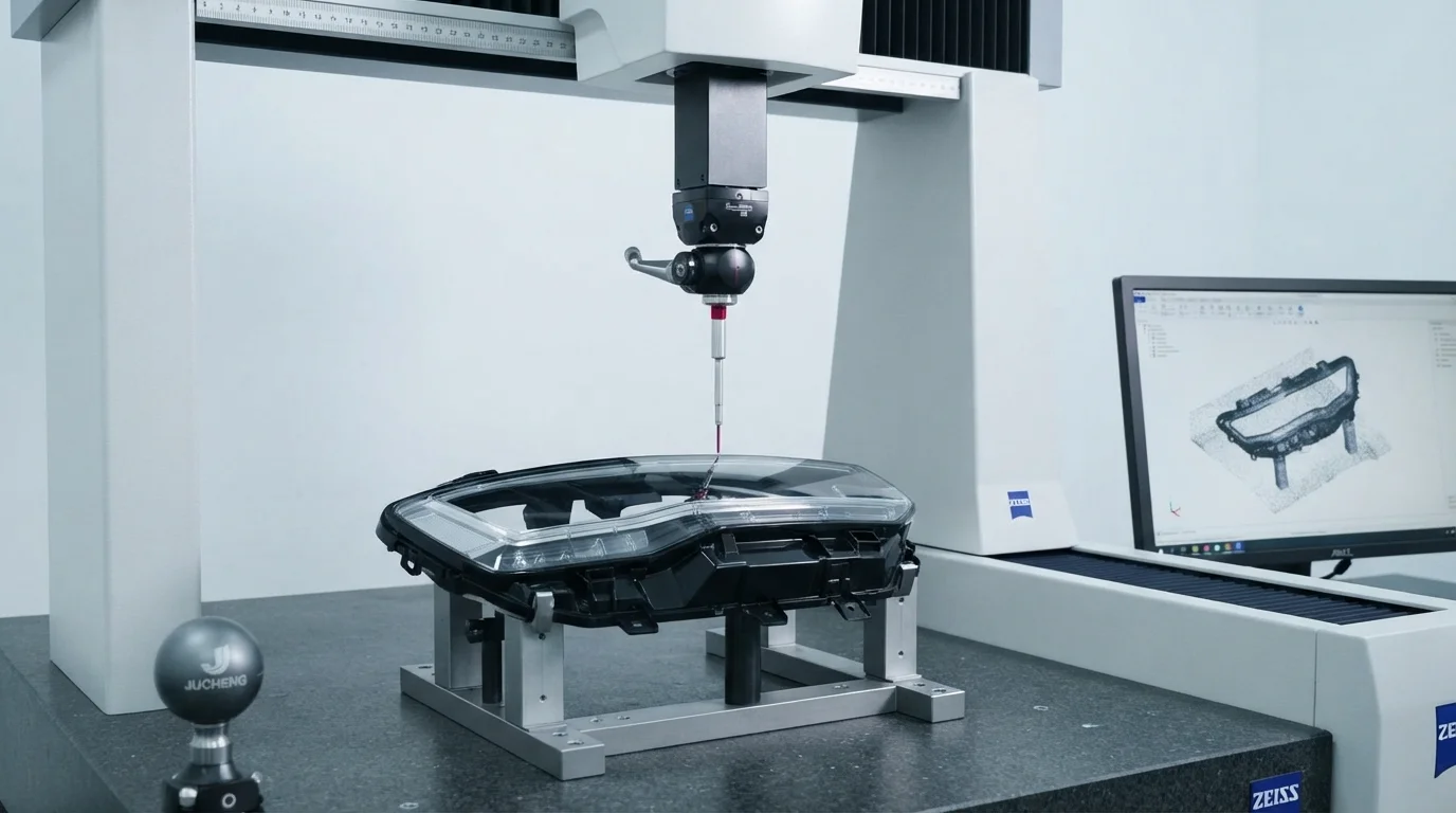
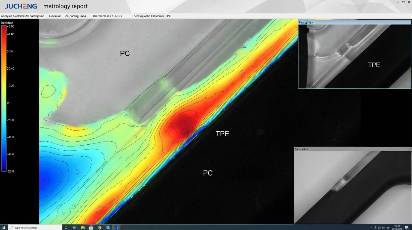
Validating complex geometric profiles on multi-material parts demands high-accuracy coordinate metrology. Metrology inspection laboratories utilize automated Zeiss CMM machines with scanning precision of ±0.003 mm to verify true position concentricity. Non-contact OGP optical measuring systems scan delicate color separation lines and soft elastomeric shut-off boundaries without applying physical contact force.
Verifying two shot injection molding tolerances under strict quality systems ensures complete batch-to-batch repeatability across high-volume production runs. Comprehensive First Article Inspection (FAI) reports and statistical process control data verify CpK > 1.67 on all critical-to-quality dimensions.
Why Choose JUCHENG for High-Precision 2K Manufacturing
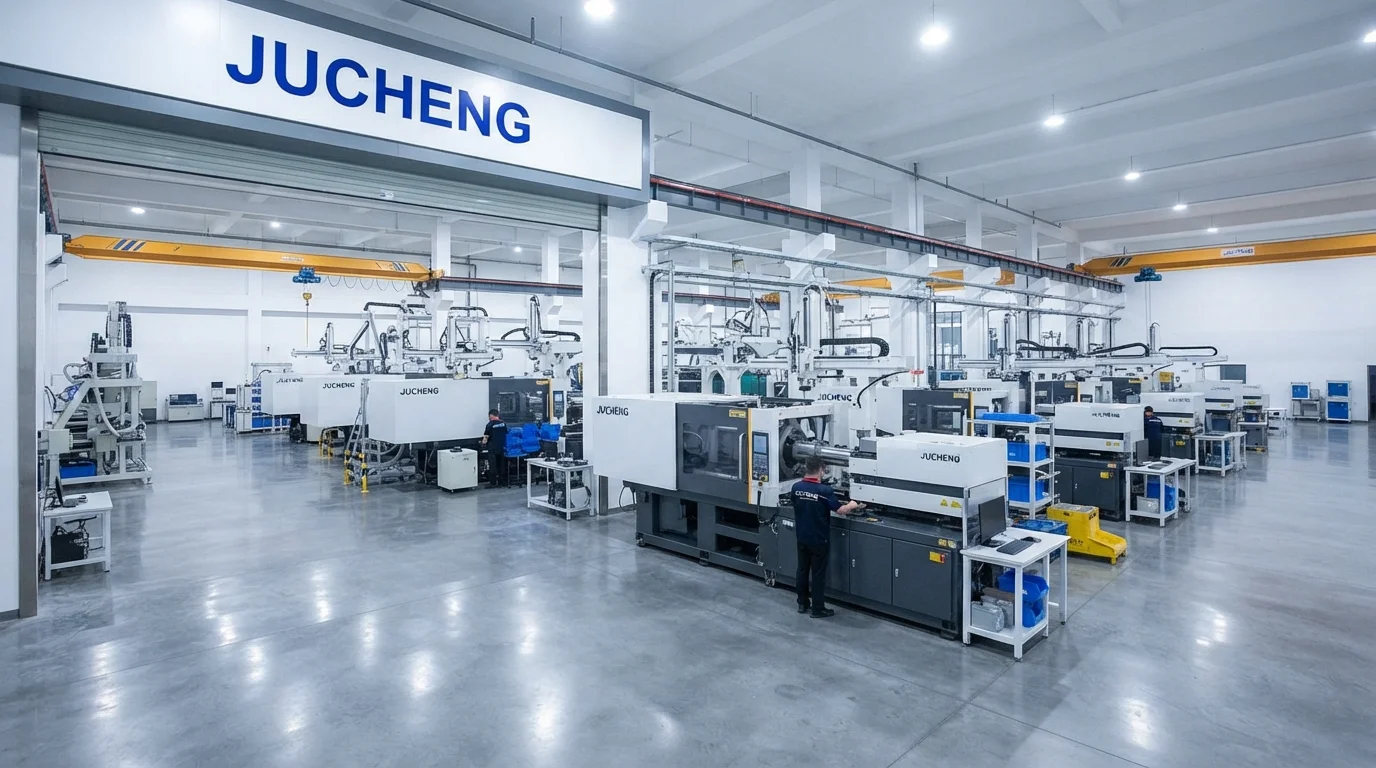
Partnering with JUCHENG provides access to an advanced manufacturing facility housing 35+ automated injection presses ranging from 15T to 3000T clamping force. Operating an in-house tool room with 25 sets of 5-axis CNC machines permits precise machining of shut-off steel lands from hardened S136 stainless steel or H13 tool steel. Quality management systems certified to IATF 16949 and ISO 13485 back every multi-shot production run, offering full PPAP Level 3 documentation for automotive programs.
Operating an ISO Class 8 cleanroom molding department protects medical components from particulate contamination during molding and drop-packaging. Maintaining tight two shot injection molding tolerances relies on in-house CNC toolmaking for two shot injection molding.
Frequently Asked Questions (FAQs)
What is a typical dimensional tolerance in two-shot injection molding?
Standard commercial tolerances for two-shot injection molding range from ±0.03 mm to ±0.05 mm across the rigid substrate and overmold boundaries. Precision tooling with CNC-ground core locating pins achieves tight tolerances down to ±0.01 mm on critical sealing steps and backlit symbols.
How do locating pins ensure rotary turntable platen repeatability?
Locating pins and tapered shot-pins engage precision ground alignment bushings on the stationary mold plate before final clamp-up. Mechanical shot-pin engagement eliminates rotary drive backlash, ensuring platen positioning repeatability within ±0.005 mm.
Why does differential shrinkage cause warpage in 2K parts?
Differential shrinkage occurs when the rigid substrate and flexible overmold contract at different rates during cooling. High contraction forces in the secondary elastomer pull on the rigid substrate wall, causing dimensional bow or twisting. Pre-compensating mold steel dimensions and balancing cooling channels resolves warpage.
How does Zeiss CMM inspection verify multi-material components?
Zeiss CMM coordinate measuring machines use ruby-tipped touch probes to scan 3D geometric coordinates with scanning accuracy of ±0.003 mm. Touch-probe scanning verifies hole pitch, insert concentricity, and substrate flatness against digital CAD nominals.
Can optical non-contact profilers measure soft TPE overmold dimensions?
Optical non-contact profilers utilize high-magnification video cameras and laser sensors to measure soft TPE features without physical contact. Physical touch probes can deflect or compress soft rubber, making non-contact optical metrology essential for elastomeric seals.
Why is mold steel hardness critical for maintaining 2K shut-off tolerances?
Hardened mold steels like S136 and H13 heat-treated to HRC 48-52 resist mechanical abrasive wear and clamping fatigue over 1,000,000 cycles. Maintaining high steel hardness prevents shut-off lands from deforming, eliminating soft elastomer flash.