
Designing multi-material polymer components requires balancing wall thickness ratios, shut-off steel angles, and mechanical anchoring features inside the 3D CAD model. Integrating flexible elastomeric layers directly over rigid plastic substrates provides tactile ergonomics, impact protection, and fluidic sealing without secondary mechanical fasteners.

Improper wall transitions or weak perimeter shut-offs trigger severe manufacturing defects like edge peeling, elastomeric flash, and localized sink marks. Establishing standardized DfM guidelines during initial 3D modeling eliminates costly tool modifications and ensures high-yield series production. This technical engineering guide analyzes wall thickness ratios, mechanical undercut geometries, and shut-off land sealing parameters.
Wall Thickness Transitions & Preventing Soft Rubber Sink Marks
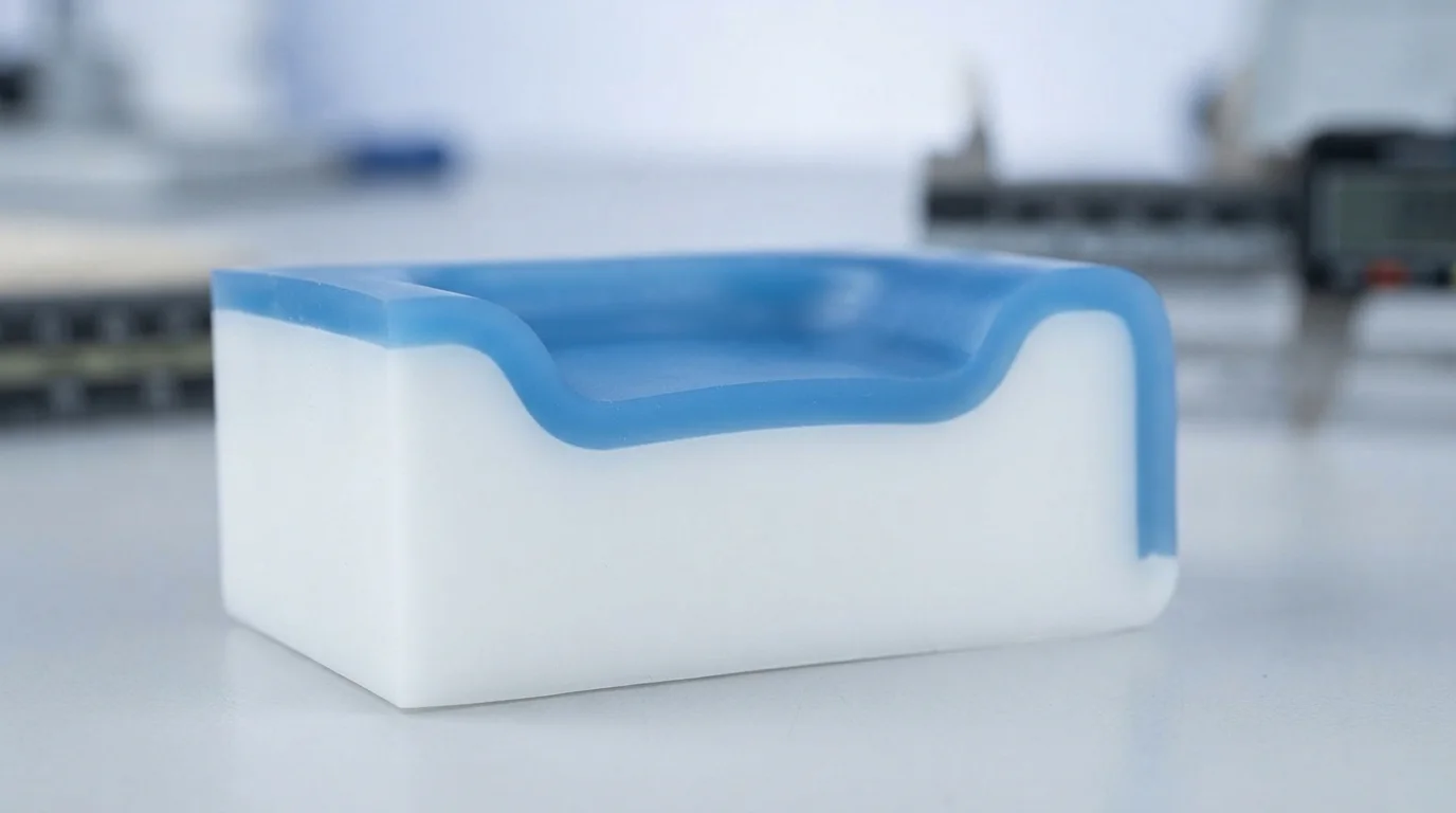
Adhering to a comprehensive overmolding design guide ensures that elastomeric layers solidify uniformly without developing cosmetic sink marks or internal voids. Nominal wall thickness for the soft エラストマー layer should remain between 1.5 mm and 3.0 mm across the component. Designing overmold sections thinner than 1.0 mm creates high injection resistance that leads to short shots in low-viscosity TPE または TPU resins.
Conversely, excessively thick elastomer sections cool significantly slower than adjacent substrate walls, pulling surface material inward to create deep sink depressions. Incorporating gradual taper transitions between thick and thin sections prevents localized mass concentrations. Maintaining uniform wall thicknesses across both substrate and overmold layers ensures balanced thermal contraction throughout the cooling cycle.
| 設計パラメータ | 推奨CADガイドライン | 違反した場合の物理的リスク | ツーリング最適化戦略 |
|---|---|---|---|
| エラストマー壁厚 | 1.5 mm – 3.0 mm 均一 | ヒケ(>3.0mm)またはショートショット(<1.0mm) | 壁段差部で2:1の半径遷移を維持 |
| 基板壁抜きテーパ角 | 1.5° – 2.0° 最小テーパ | 部品の引きずり擦り傷とコアピン固着 | 深いコア引き抜きキャビティの抜きテーパを増加 |
| 外周エッジ段差高さ | ≥ 0.5 mm 90度段差 | エラストマーエッジのフェザリングと剥離 | 明確なシャットオフ着座ショルダーの機械加工 |
Designing Mechanical Interlocks, Holes, and Undercuts
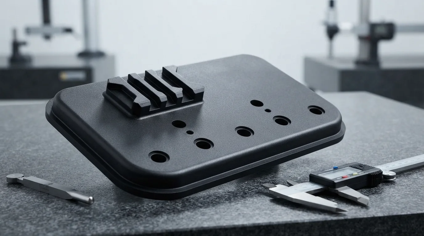
ポリマー間の化学的接着は、部品が強力な洗浄剤、湿気、または動的な繰り返しせん断力にさらされると、時間の経過とともに劣化する可能性があります。 機械的インターロック を剛性プラスチック基板に組み込むことで、剥離を防ぐ永続的な物理的保持が得られます。90度のダブテール溝、アンダーカット、貫通穴を設計することで、溶融エラストマーが基板を通過して反対側でロックできるようになります。.
ガラス充填材入りエンジニアリングプラスチックなどの基板は、 PA66 または ポリカーボネート(PC) 機械的ロッキングチャネルから大きな恩恵を受けます。機械的アンカーは柔軟なオーバーモールドを機械的に捕捉し、大きな引張力や剥離力がかかっても端部の浮き上がりをゼロにします。このオーバーモールド設計ガイドに従うことで、自動車や医療の長期ライフサイクルにわたって界面剥離のリスクを最小限に抑えられます。.
機械的アンカーリング設計ルールは以下の通りです:
- ダブテール溝の配置—周辺エッジに沿ってアンダーカットチャネルを機械加工することで、動的な剥離力に対してエラストマーをロックします。.
- 貫通フローポート—コア貫通穴を設けることで、セカンドショットの溶融物が基板を通過し、両側でリベット留めできます。.
- コーナー半径の最適化—内部コーナーを最小0.5 mmの半径で丸めることで、局所的な応力集中を排除します。.
- 基板ポケット深さ—ポケット深さを所望のエラストマー厚さと等しく保つことで、外面をフラットに仕上げます。.
エラストマーのフラッシュを防ぐシャットオフランド設計
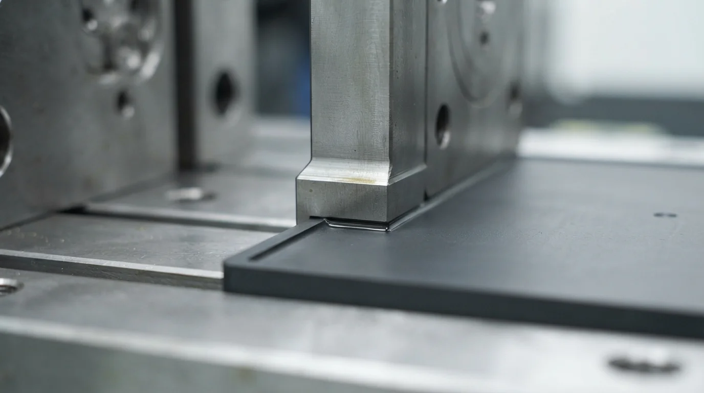
Applying principles from an overmolding design guide prevents low-viscosity soft resins from leaking past cavity boundaries during secondary injection. Mold shut-off steel clamps directly against the pre-molded substrate to seal the overmold cavity. Designing flat シャットオフランド with a minimum width of 0.5 mm to 1.0 mm provides a positive mechanical barrier against molten rubber flow.
Incorporating a 90-degree edge step measuring at least 0.5 mm deep along the overmold perimeter creates a sharp cutoff line. Sharp cutoff steps hide transition seams and prevent soft rubber from feathering into razor-thin edges that peel easily. Precision tool steel fitment ensures clean, cosmetic separation lines between rigid and flexible polymer boundaries.
Why Choose JUCHENG for Overmolding DfM & Tooling
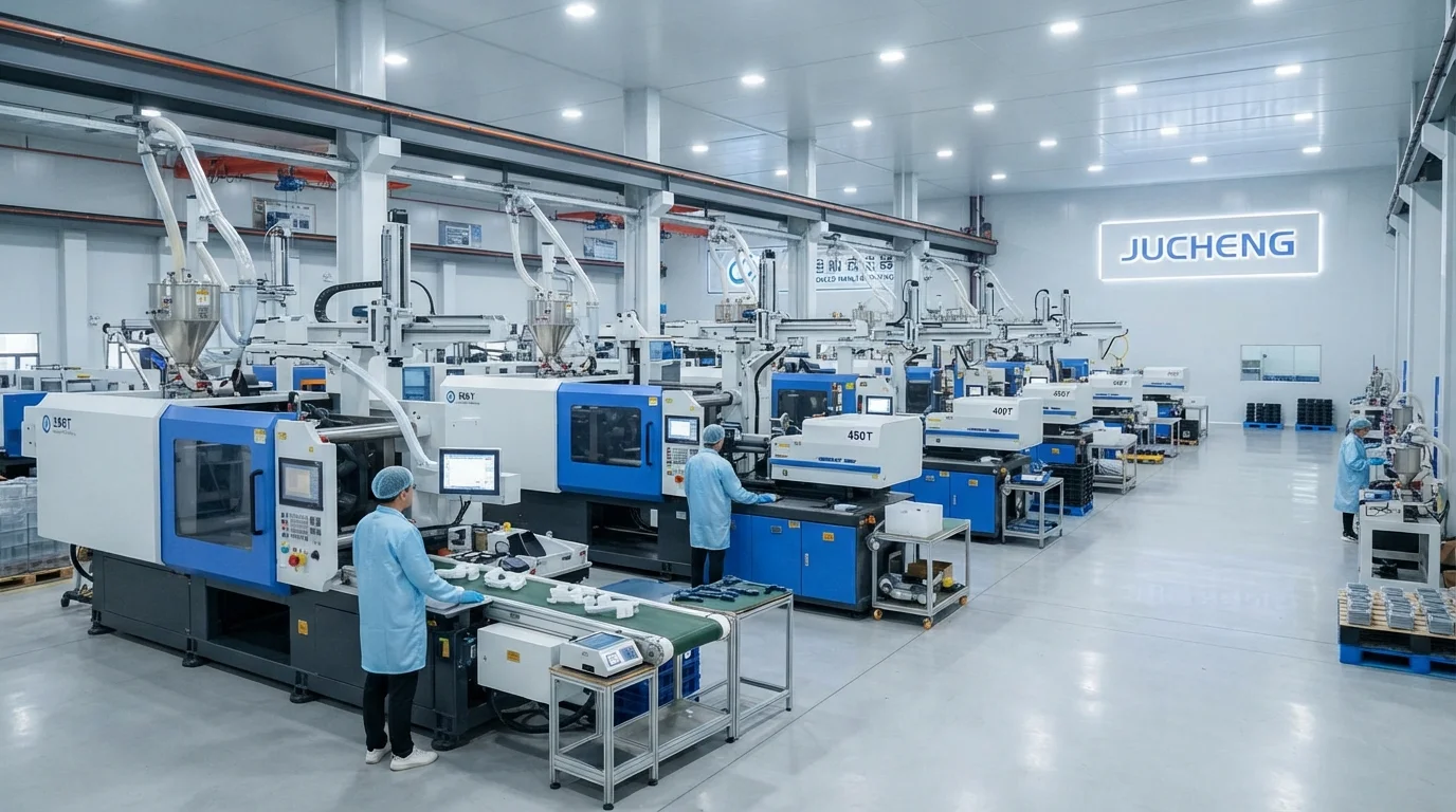
Partnering with JUCHENG for multi-material encapsulation projects provides access to an extensive production floor equipped with 35+ automated injection presses ranging from 15T to 3000T clamping force. Operating an in-house tool room with 25 sets of 5-axis CNC machines permits precise machining of shut-off steel lands from hardened S136ステンレス鋼 または H13工具鋼. Our engineering team delivers a free 24-hour DfM review for every CAD submission, analyzing substrate wall thickness, draft angles, and shut-off feasibility before cutting steel.
Adhering to a strict overmolding design guide minimizes tooling revisions during オーバーモールディング射出成形. IATF 16949およびISO 13485認証の品質管理システムがすべてのマルチショット生産を支え、自動車プログラム向けの完全なPPAPレベル3文書を提供します。ISOクラス8のクリーンルーム成形部門を運営し、成形およびドロップパッケージング中の医療部品を粒子汚染から保護します。.
よくある質問 (FAQ)
What is the ideal wall thickness for TPE and TPU overmolding?
Ideal wall thickness for TPE and TPU overmolding layers ranges from 1.5 mm to 3.0 mm. Thinner walls below 1.0 mm increase flow resistance and risk short shots, while thicker walls above 4.0 mm cause prolonged cooling cycles and cosmetic sink marks.
Why are mechanical undercuts recommended in overmolding CAD design?
Mechanical undercuts like dovetail grooves and through-holes physically lock the elastomer onto the rigid substrate. Physical anchoring ensures that soft grips and seals remain permanently attached even if chemical bonding weakens under thermal cycling or chemical exposure.
How do shut-off lands prevent elastomer flash on cosmetic surfaces?
Tooling shut-off lands clamp firmly against the rigid substrate along a 0.5 mm to 1.0 mm wide sealing face. Designing a 90-degree step along the perimeter creates a sharp cutoff edge that blocks molten elastomer from bleeding over appearance faces.
Can sharp internal corners cause overmolded elastomer peeling?
Sharp internal corners create localized stress concentrations and impede smooth elastomer flow. Adding generous radii (minimum 0.5 mm) at all transition corners promotes uniform melt packing and enhances interfacial bond durability.
How does substrate preheating improve overmolding adhesion?
Preheating the rigid plastic substrate to 70°C-90°C slows the cooling rate of the incoming second-shot melt. Warm boundary surfaces allow polymer chains from both materials to interdiffuse deeply, forming a strong chemical fusion bond.
Why is an early DfM review essential before cutting overmolding mold steel?
Conducting an early DfM review evaluates nominal wall thicknesses, shut-off angles, and gate placements while the design is still digital. Identifying potential flash or sink risks early eliminates costly mold rework and long tooling delays.