
Designing multi-material polymer components requires balancing wall thickness ratios, shut-off steel angles, and mechanical anchoring features inside the 3D CAD model. Integrating flexible elastomeric layers directly over rigid plastic substrates provides tactile ergonomics, impact protection, and fluidic sealing without secondary mechanical fasteners.

Improper wall transitions or weak perimeter shut-offs trigger severe manufacturing defects like edge peeling, elastomeric flash, and localized sink marks. Establishing standardized DfM guidelines during initial 3D modeling eliminates costly tool modifications and ensures high-yield series production. This technical engineering guide analyzes wall thickness ratios, mechanical undercut geometries, and shut-off land sealing parameters.
Wall Thickness Transitions & Preventing Soft Rubber Sink Marks
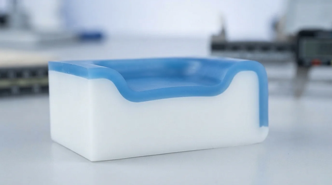
Adhering to a comprehensive overmolding design guide ensures that elastomeric layers solidify uniformly without developing cosmetic sink marks or internal voids. Nominal wall thickness for the soft elastomer layer should remain between 1.5 mm and 3.0 mm across the component. Designing overmold sections thinner than 1.0 mm creates high injection resistance that leads to short shots in low-viscosity TPE ou en TPU resins.
Conversely, excessively thick elastomer sections cool significantly slower than adjacent substrate walls, pulling surface material inward to create deep sink depressions. Incorporating gradual taper transitions between thick and thin sections prevents localized mass concentrations. Maintaining uniform wall thicknesses across both substrate and overmold layers ensures balanced thermal contraction throughout the cooling cycle.
| Paramètre de conception | Directive CAO recommandée | Physical Risk if Violated | Stratégie d'optimisation de l'outillage |
|---|---|---|---|
| Elastomer Wall Thickness | 1,5 mm – 3,0 mm uniforme | Sink marks (>3.0mm) or short shots (<1.0mm) | Maintain 2:1 radius transitions at wall steps |
| Substrate Wall Draft Angle | Dépouille minimale de 1,5° – 2,0° | Part drag scuffs & core pin binding | Increase draft for deep core draw cavities |
| Perimeter Edge Step Height | ≥ 0.5 mm 90-Degree Step | Elastomer edge feathering & peeling | Machining distinct shut-off landing shoulders |
Designing Mechanical Interlocks, Holes, and Undercuts
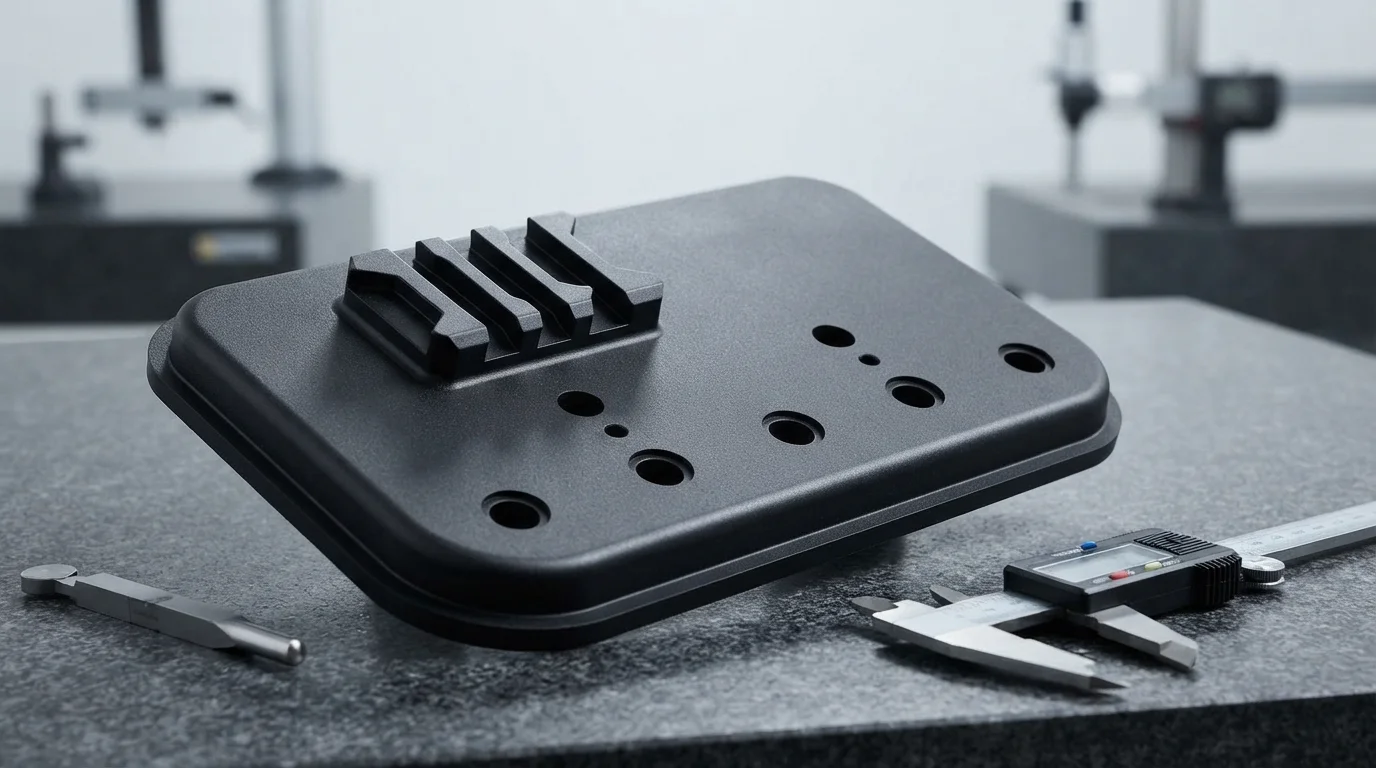
Chemical adhesion between polymers can degrade over time when components face aggressive cleaning chemicals, moisture, or dynamic cyclic shear. Incorporating verrous mécaniques into the rigid plastic substrate provides permanent physical retention that prevents delamination. Designing 90-degree dovetail grooves, undercuts, and through-holes allows molten elastomer to flow through the substrate and lock on the opposite side.
Substrates molded from engineering plastics like glass-filled PA66 ou en polycarbonate (PC) optique benefit substantially from mechanical locking channels. Mechanical anchors trap the flexible overmold mechanically, ensuring zero edge lifting under heavy tensile or peeling forces. Following this overmolding design guide minimizes interfacial peeling risks across extended automotive and medical lifecycles.
Mechanical anchoring design rules include:
- Dovetail groove placement—Machining undercut channels along perimeter edges locks the elastomer against dynamic peel forces.
- Through-hole flow ports—Creating core through-holes permits second-shot melt to flow through the substrate and rivet on both sides.
- Corner radius optimization—Rounding internal corners with a minimum 0.5 mm radius eliminates localized stress risers.
- Substrate pocket depth—Maintaining pocket depths equal to desired elastomer thickness ensures flush outer surfaces.
Shut-off Land Design to Prevent Elastomer Flash
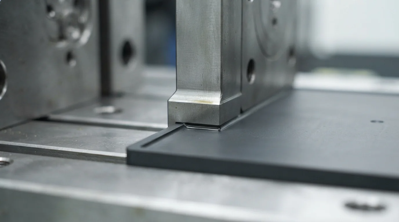
Applying principles from an overmolding design guide prevents low-viscosity soft resins from leaking past cavity boundaries during secondary injection. Mold shut-off steel clamps directly against the pre-molded substrate to seal the overmold cavity. Designing flat portées d'arrêt with a minimum width of 0.5 mm to 1.0 mm provides a positive mechanical barrier against molten rubber flow.
Incorporating a 90-degree edge step measuring at least 0.5 mm deep along the overmold perimeter creates a sharp cutoff line. Sharp cutoff steps hide transition seams and prevent soft rubber from feathering into razor-thin edges that peel easily. Precision tool steel fitment ensures clean, cosmetic separation lines between rigid and flexible polymer boundaries.
Why Choose JUCHENG for Overmolding DfM & Tooling
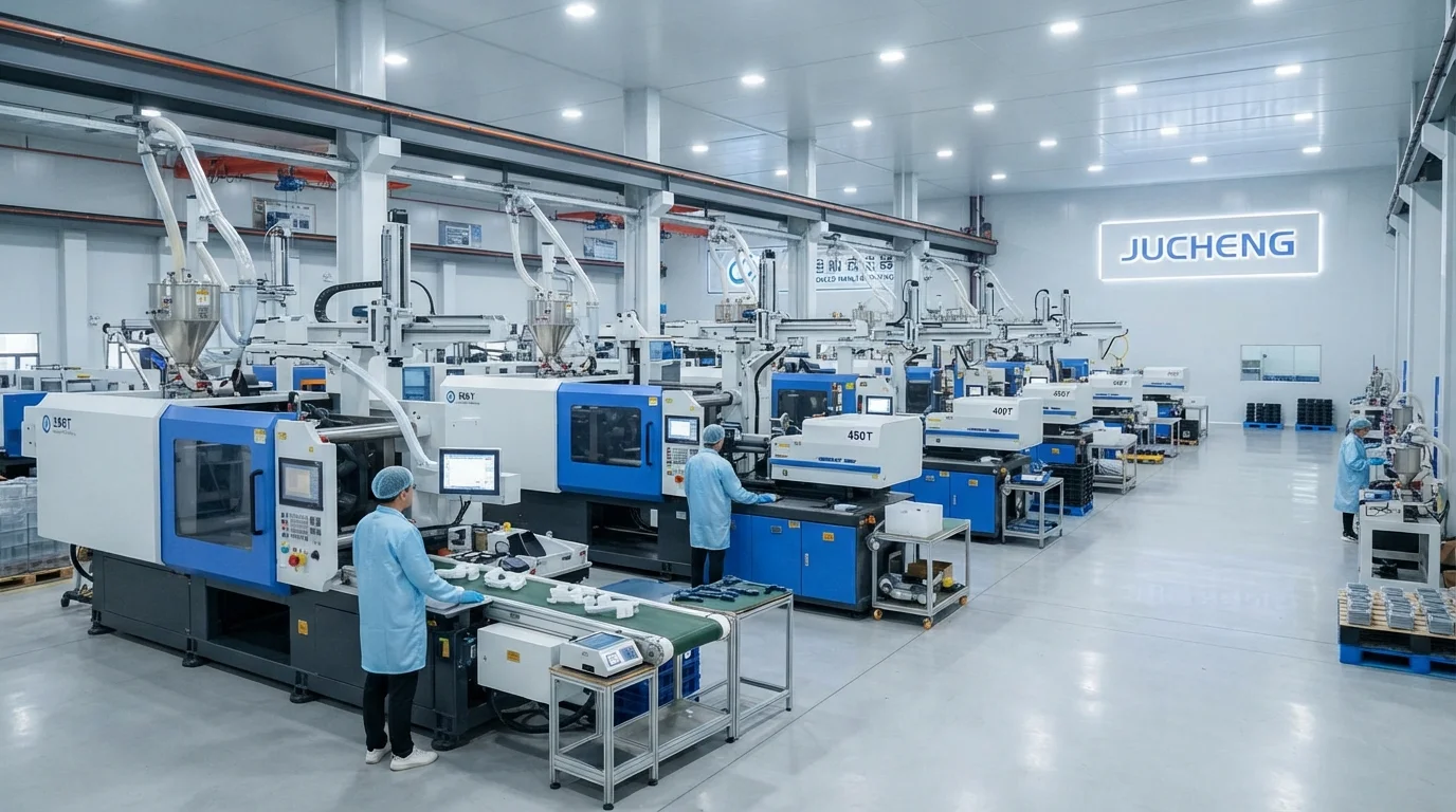
Partnering with JUCHENG for multi-material encapsulation projects provides access to an extensive production floor equipped with 35+ automated injection presses ranging from 15T to 3000T clamping force. Operating an in-house tool room with 25 sets of 5-axis CNC machines permits precise machining of shut-off steel lands from hardened Acier inoxydable S136 ou en de l'acier à outils H13. Our engineering team delivers a free 24-hour DfM review for every CAD submission, analyzing substrate wall thickness, draft angles, and shut-off feasibility before cutting steel.
Adhering to a strict overmolding design guide minimizes tooling revisions during moulage par injection de surmoulage. Les systèmes de management de la qualité certifiés IATF 16949 et ISO 13485 soutiennent chaque production multi-shots, offrant une documentation complète PPAP niveau 3 pour les programmes automobiles. L'exploitation d'un département de moulage en salle blanche ISO classe 8 protège les composants médicaux contre la contamination particulaire pendant le moulage et l'emballage en vrac.
Questions fréquemment posées (FAQ)
What is the ideal wall thickness for TPE and TPU overmolding?
Ideal wall thickness for TPE and TPU overmolding layers ranges from 1.5 mm to 3.0 mm. Thinner walls below 1.0 mm increase flow resistance and risk short shots, while thicker walls above 4.0 mm cause prolonged cooling cycles and cosmetic sink marks.
Why are mechanical undercuts recommended in overmolding CAD design?
Mechanical undercuts like dovetail grooves and through-holes physically lock the elastomer onto the rigid substrate. Physical anchoring ensures that soft grips and seals remain permanently attached even if chemical bonding weakens under thermal cycling or chemical exposure.
How do shut-off lands prevent elastomer flash on cosmetic surfaces?
Tooling shut-off lands clamp firmly against the rigid substrate along a 0.5 mm to 1.0 mm wide sealing face. Designing a 90-degree step along the perimeter creates a sharp cutoff edge that blocks molten elastomer from bleeding over appearance faces.
Can sharp internal corners cause overmolded elastomer peeling?
Sharp internal corners create localized stress concentrations and impede smooth elastomer flow. Adding generous radii (minimum 0.5 mm) at all transition corners promotes uniform melt packing and enhances interfacial bond durability.
How does substrate preheating improve overmolding adhesion?
Preheating the rigid plastic substrate to 70°C-90°C slows the cooling rate of the incoming second-shot melt. Warm boundary surfaces allow polymer chains from both materials to interdiffuse deeply, forming a strong chemical fusion bond.
Why is an early DfM review essential before cutting overmolding mold steel?
Conducting an early DfM review evaluates nominal wall thicknesses, shut-off angles, and gate placements while the design is still digital. Identifying potential flash or sink risks early eliminates costly mold rework and long tooling delays.