
Injection molding cycle time is the elapsed production interval between completed shots. It is not just cooling time: filling, packing, mold movement, ejection and handling steps all affect the repeatable cycle. For a buyer, the useful number is the cycle that consistently produces acceptable parts under the agreed material, tooling, cavity and inspection conditions, not the shortest setting seen during a trial.
That distinction matters because a shorter cycle can look attractive on a quote while hiding a quality trade-off. A part that sticks, warps, varies in weight or needs extra inspection may cost more than one made on a slightly longer, stable cycle.
Quick answer: start by separating the cycle into its actual stages, then identify which stage limits the part. Cooling is often a major contributor, but wall thickness, resin behavior, gate freeze, mold temperature, ejection and automation can change the picture.
In this guide:
- What cycle time measures
- The stages that shape a shot
- Why cooling is not the whole story
- When a faster cycle creates risk
- How to compare cycle-time claims
- FAQs
What Injection Molding Cycle Time Actually Measures
A production cycle is the time from one shot to the next under a defined process. The machine-displayed cycle may not include every downstream activity. Robot removal, trimming, inspection, part cooling outside the mold or packaging can happen in parallel, or become the real constraint, so buyers should clarify what the quoted figure includes.
When teams compare two cycle figures, they should compare the same part revision, resin grade, number of cavities, mold temperature, acceptance criteria and removal method. Otherwise, the faster number may describe a different job rather than a better process.
Follow the Shot: Which Stages Set the Cycle?
The cycle contains several linked stages. Their timing depends on the part, mold and process window, and some machine actions can overlap.
- Close and clamp: the mold closes and reaches the required clamping condition. Mold protection and safe closure are part of a repeatable cycle.
- Fill: molten resin travels through the runner and gate into the cavity. Flow length, wall transitions, gate design, venting and resin viscosity influence how the cavity fills.
- Pack and hold: pressure compensates for material shrinkage while the gate remains able to transmit pressure. The useful hold period is tied to gate freeze and part response, not simply a longer timer.
- Cool: the part must become stable enough to eject without unacceptable distortion, sticking or surface damage. The required time depends on geometry, resin, mold temperature and cooling layout.
- Open and eject: the mold opens and the part is released. Deep cores, undercuts, delicate features or manual handling can make ejection and removal the limiting step.
These stages are not always a simple sum. For example, screw recovery may overlap with cooling on some machine setups. That is why a cycle review should use the machine sequence and part evidence, not a generic formula detached from the actual process.
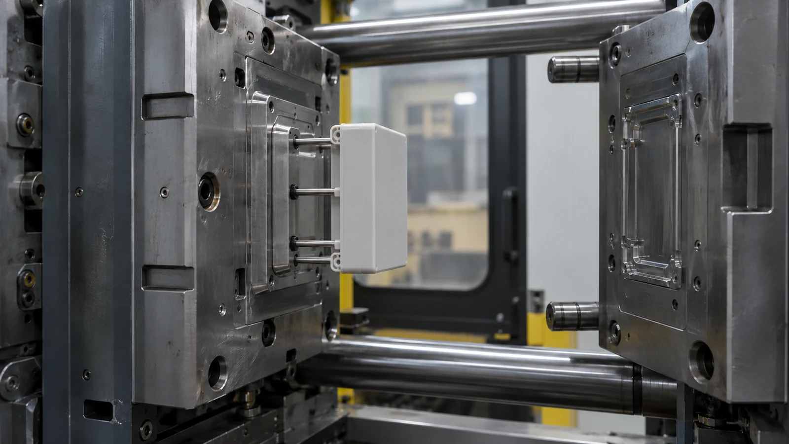
Why Cooling Often Dominates, but Not Always
Thicker sections usually retain heat longer than thin walls, while uneven wall transitions can create different cooling and shrinkage behavior in one part. Resin thermal properties, mold temperature, cooling-channel placement and contact between the part and steel also matter. A cooling change that helps one area can leave another area hot or increase distortion.
Gate freeze is another useful boundary. Once the gate can no longer transmit packing pressure, extending hold time may add little to the part. But reducing hold or cooling without checking part weight, dimensions and appearance can create sink, voids, warpage or ejection problems. The correct setting must be established for the selected resin and geometry.
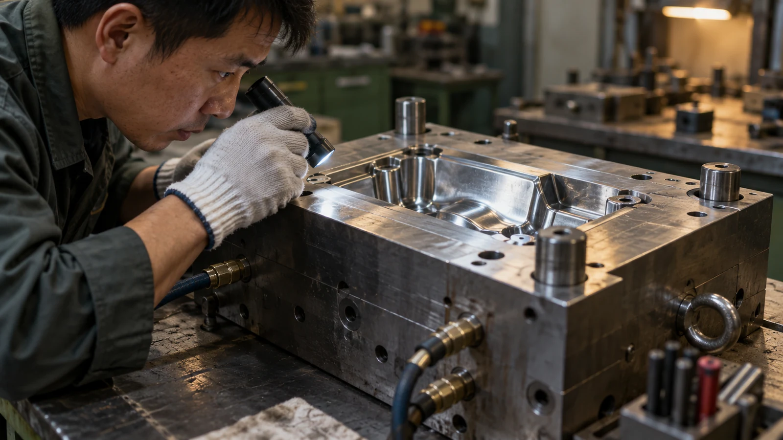
For a complex part, cycle-time work should be reviewed alongside the broader plastic injection molding process and controls. The best cycle is the fastest repeatable cycle that remains inside the approved quality window.
When a Faster Cycle Creates a Quality Risk
A shorter timer is not a win if parts leave the mold too hot to hold their shape or if the process becomes sensitive to small material or temperature changes. Watch for signs such as rising ejection force, sticking, bent ribs, dimensional drift after ejection, changing part weight, or appearance defects that appear only after a speed adjustment.
Change one factor at a time and retain samples from before and after the adjustment. If a cycle reduction changes several stages at once, it becomes difficult to tell whether the improvement came from cooling, hold, motion overlap or a changed acceptance threshold.
Where launch timing depends on process readiness, a structured mold trial and validation plan helps establish what was tested, which dimensions matter and what conditions define an acceptable run.
How Buyers Should Compare Cycle-Time Claims
Ask for a like-for-like comparison rather than a stand-alone number. A practical review should capture:
- Part revision, resin grade and any reinforcement or colorant.
- Number of cavities producing acceptable parts in the quoted cycle.
- Whether robot handling, trimming or other secondary steps are included.
- Key acceptance checks, sample size and how dimensional stability is assessed.
- Whether the figure is a trial observation or a repeatable production target.
These details help procurement compare cost and capacity on equal terms. They also make it easier to discuss a realistic improvement target with engineering instead of asking a supplier to reduce cycle time without defining what must remain unchanged.
Frequently Asked Questions
Is cooling time the same as cycle time?
No. Cooling is one stage. Cycle time also includes filling, packing or holding, mold movement and ejection; some machine operations may overlap.
Does a shorter cycle always lower part cost?
Not necessarily. It can improve output if the same number of conforming parts is produced consistently. Scrap, extra inspection, handling delays or instability can erase the apparent gain.
Which part feature most affects cooling?
There is no universal single feature. Wall thickness and uneven section changes are important, but resin, mold temperature, cooling-channel layout, gate location and ejection requirements also affect the result.
What should I provide for a cycle-time review?
Share the 3D model and drawing revision, resin grade, expected volume, critical dimensions, appearance requirements and any known cycle or ejection issues. Those inputs make the discussion specific to the part.