
Short answer: Design plastic parts for vacuum metallization around the finished coated surface, not only the bare molded geometry. Define which faces receive metal, how edges and recesses will be coated or masked, what the substrate must look like before coating, and how coating thickness and handling affect fit. Then confirm the complete coating stack and acceptance criteria with the finishing supplier on representative parts.
These plastic vacuum metallization design considerations apply to decorative and functional-looking metallic finishes on injection-molded plastic. Vacuum metallization is a family of vacuum-deposition approaches; the exact metal layer, pretreatment, primer and protective topcoat depend on the supplier’s process and the product requirement. Do not treat “metallic finish” as a complete material or performance specification.
See our vacuum metallization service and broader surface finishing options for the relevant process scope. A finishing provider such as G.W.P. describes vacuum coating for decorative plastic metallization; the chosen vendor should confirm the actual stack and capability for your part.
In this article:
- Define what the metal appearance must do
- Shape the part for coating access
- Protect the substrate and interfaces
- Qualify the finish on the real part
- Frequently asked questions
Define What the Metal Appearance Must Do
First decide whether the finish is purely visual or also carries a measurable function. A decorative bright surface, a partially metallized reflector, a shield or a conductive area can require different coating boundaries and tests. State the required appearance, color, gloss, reflectivity or electrical performance only where it can be measured and accepted. A silver appearance alone does not prove that a part is conductive or provides a specified barrier.
Mark coated, uncoated and masked regions on the CAD model. Identify the primary viewing direction and the faces that may be hidden after assembly. If a metallic layer must stop at a crisp edge, show where the boundary belongs and how much variation is acceptable. A line that looks precise on a drawing may be difficult to reproduce over a curved transition or a flexible mask edge.
Also distinguish the visual target from the sample approval method. Metallic surfaces can look different as lighting direction, viewing angle and surrounding colors change. Approve a physical reference part under agreed conditions, and specify whether color or gloss is judged visually or with an instrument. Avoid relying on an uncalibrated monitor image for final acceptance.
Shape the Part for Coating Access
Vacuum deposition and its supporting coating steps require the part to be presented to the process in a defined orientation. Deep pockets, narrow slots, sharp re-entrant corners and hidden faces may receive a different appearance from the directly exposed show surface. Ask the supplier how the part is fixtured, rotated or masked and which surfaces are line-of-sight limited in the selected process.
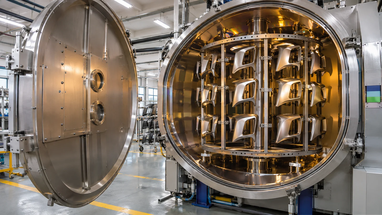
Where the design allows, keep the primary show surface open and avoid placing a critical metallic boundary deep inside a recess. Use transitions that are accessible to the coating setup and easy to inspect. If a recess is essential for function, decide whether its interior must be metallized, can remain uncoated, or needs a different specified appearance. The answer affects mask design, fixtures and acceptance zones.
Consider the full production sequence, including molding, coating, handling and assembly. A delicate high-gloss face may need a protected resting surface or a no-contact region for fixtures. A clip, snap, screw boss or press-fit feature may damage a coating if it is placed on a coated interface or flexes the substrate during assembly. Review those contact surfaces on the assembly model before freezing the part.
| Part detail | Question for the coating supplier | Design action |
|---|---|---|
| Deep recess | Can the process coat and inspect the required interior surface? | Define the required coverage or leave the area outside the cosmetic zone |
| Coating edge | How is the boundary masked and what edge variation is feasible? | Place the boundary on a stable, accessible transition |
| Snap or press-fit | Will assembly stress crack, scuff or distort the coated region? | Keep high-strain contact away from critical coated faces where practical |
| Large show face | How will fixtures support it without marks? | Identify allowed support and handling zones in the model |
Protect the Substrate and Interfaces
The final appearance reflects the molded surface beneath the metal layer and any primer or basecoat. Sink, flow lines, weld lines, scratches, fingerprints, mold-release residue and texture variation can remain visible or affect the coating system. A reflective finish may make small changes in surface quality easier to see. Define the allowable molded substrate condition separately from the coating appearance.

Resin choice must be compatible with the complete finish system and the product’s service environment. A coating supplier may use cleaning, surface activation, primer or a leveling layer before deposition, then apply a protective topcoat. The sequence is supplier-specific; confirm whether it is compatible with the chosen resin grade, pigment, molded texture and temperature exposure. Do not assume a process qualified on one polymer grade will automatically transfer to another.
Account for the coating in fit and appearance interfaces. Even when each deposited layer is thin, primer and protective layers can affect edge definition, opening clearance, mating faces and reflective appearance. Ask for the supplier’s coating build range and tolerance contribution, then identify dimensions that should be measured before coating, after coating or after assembly. The correct datum scheme depends on the part and its functional interfaces.
Qualify the Finish on the Real Part
- Release a finish map. Mark show surfaces, masked zones, functional contact areas, boundaries and inspection locations on a controlled 3D model.
- Agree the coating stack. Record substrate grade, surface preparation, primer or basecoat, deposited layer and protective topcoat as applicable. Identify which supplier owns each material and process change.
- Make representative molded samples. Include the real texture, gate location, geometry and molding condition. A hand-polished flat plaque can screen appearance but cannot represent all molded features.
- Test the relevant use conditions. Select abrasion, cleaning, humidity, temperature, adhesion or electrical tests only when they correspond to the product requirement. Define test method, locations and acceptance before trial.
- Check assembly and handling. Inspect parts after normal fixturing, packaging and assembly operations. A finish that passes as a loose sample may still be vulnerable at clips, mating edges or contact points.
When a trial shows a defect, record where it occurs and whether it follows the geometry, mold cavity, fixture orientation or masked boundary. That helps distinguish a design-access problem from substrate condition or coating-process variation. Change one major factor at a time where practical so the next trial teaches the team something.
Frequently Asked Questions
Does vacuum metallization make a plastic part conductive?
Not automatically. Decorative metallic appearance and electrical conductivity are separate requirements. If conductivity or shielding is needed, specify the required measurement and validate the coating system on the intended surfaces and geometry.
Can every surface of a molded part be metallized?
Coverage depends on the deposition method, part orientation, geometry, masking and coating sequence. Deep or hidden features may be difficult to coat uniformly. Ask the supplier to review the CAD model and identify accessible, limited and masked areas before tooling.
Will the coating hide molding marks?
Do not assume so. Reflective finishes can make substrate variation more visible, and defects may also affect adhesion or coating uniformity. Agree the molded-surface standard before coating and inspect production-intent samples.