
Short answer: Reliable in-mold labeling starts by designing the label and molded part as one system. Lock the graphic boundary, formed shape, label material, resin interface, gate and vent strategy, and placement inspection before tooling. A flat artwork proof alone cannot show whether a label will locate cleanly on a curved wall or remain visually acceptable after molding.
These in mold labeling design guidelines are for product engineers, packaging designers and sourcing teams who need to move from artwork to a manufacturable molded component. They focus on decisions that are still inexpensive to change in CAD and in the label dieline.
For process scope and project review, see our in-mold labeling service and the wider surface finishing options. The In-Mold Decorating Association also provides a useful IML getting-started guide covering label placement, mold and handling considerations.
In this article:
- Map the label onto the real part
- Protect the artwork at boundaries
- Coordinate label, resin and tool
- Define how the result will be accepted
- Frequently asked questions
Map the Label Onto the Real Part
Begin with the three-dimensional molded geometry, not just the printable panel. Mark the intended label area on the CAD model and identify every transition it crosses: corners, taper, ribs, openings, shoulders, bottom radii and parting lines. A broad, shallow wall is generally easier to decorate consistently than a deep or strongly curved surface, but the actual label stock and placement method determine what is feasible.

For a tapered container, confirm how the artwork wraps around the wall and where its edges meet. For a multi-sided tub or housing, decide whether the graphic is one wraparound label or separate panels. A gap, overlap or seam may be acceptable, but it should be deliberate, located away from the focal graphic and represented in the approved artwork. Do not leave the label printer, mold designer and brand team to infer the same boundary independently.
Check the surface from the viewer’s normal position. The part may sit on a shelf, be held in a user’s hand, or be assembled behind a transparent cover. That viewing condition affects which label edge, placement shift or distortion is noticeable. Identify critical visual zones and secondary zones before asking for a quotation or a tolerance.
Protect the Artwork at Boundaries
Keep important text, barcodes, logos and fine registration features away from die-cut edges, gates and regions that will stretch during forming. The required clearance is not universal: it varies with label construction, printing process, die-cut tolerance, forming behavior and the part. Ask the label supplier for a dieline with a defined safe area and then compare it with the final 3D part, not a nominal flat rectangle.
Artwork with a high-contrast border can make small placement variation look larger than it is. If a frame or color band runs close to the label edge, the eye quickly detects uneven margins. Consider a border that terminates before a seam, or use a graphic layout that does not create a visual ruler along a variable boundary. Where color matching matters, approve a physical standard under agreed lighting rather than relying only on a screen image.
Review the artwork after forming if the label must follow a curved surface. A circle may become oval; type may stretch; and a logo can shift relative to an opening. Flat print approval should therefore be treated as an input, not final acceptance. Include a formed-sample review before locking the production artwork.
Coordinate Label, Resin and Tool
Successful placement depends on more than the label perimeter. The mold needs a repeatable way to receive and hold the label before the melt arrives. Depending on the part and process, retention may rely on vacuum, electrostatic charge, a locating feature or another supplier-defined method. Each method has implications for mold details, surface cleanliness, label handling and maintenance. Confirm it with the team responsible for the actual tool and production sequence.
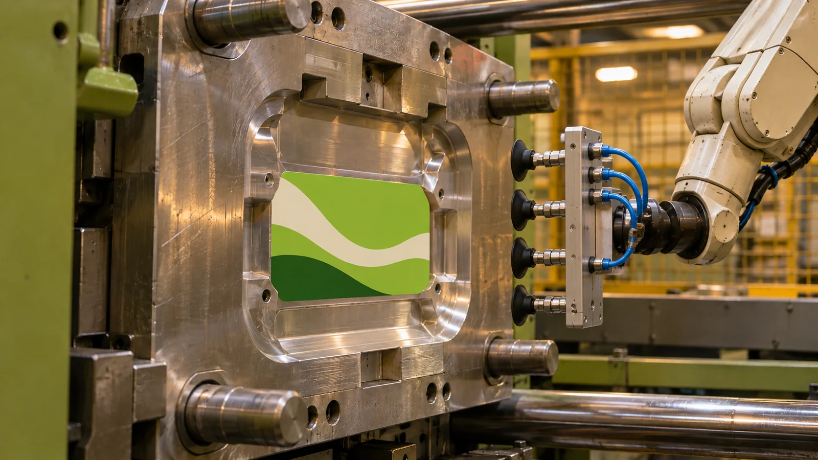
Review gate position against the decorated face. A gate that sends a fast-moving melt front across a label edge can increase the risk of movement, wrinkles or trapped air; a gate can also leave a visible vestige or disrupt the graphic. Vents, shutoffs and the label boundary should be reviewed together so that air can escape without creating an unwanted mark in a show area.
Material compatibility must be assessed for the complete stack: label film, print, coatings or adhesive if used, molded resin and colorants. Similar resin families may help in some designs, but they do not automatically guarantee bonding, appearance or recyclability. Confirm process-temperature compatibility, surface adhesion requirements, chemical exposure and end-of-life claims with the relevant suppliers.
| Design review item | Question to resolve | Evidence to request |
|---|---|---|
| Label area | Does the label cross a corner, taper, seam or opening? | Approved 3D overlay and dimensioned dieline |
| Artwork | Which text, code and graphic zones are critical? | Formed artwork proof and safe-area definition |
| Mold interface | How are label position, retention, venting and gate flow controlled? | Tool concept review and trial plan |
| Acceptance | How are position and cosmetic defects judged? | Written limits, viewing setup and sample standard |
Define How the Result Will Be Accepted
Make inspection repeatable. Specify the datum or molded feature from which label position is measured, the direction of measurement, and whether the check applies per cavity. For cosmetic evaluation, define viewing distance, lighting, angle and the conditions under which a wrinkle, edge lift, bubble, color variation or print distortion is rejectable. These details make the specification usable at first-off inspection and during production.
Build validation around the failure modes that matter to the product. A package may need checks for label placement, legibility, scuffing and exposure to expected contents or handling. A durable housing may need tests for abrasion, cleaning agents, heat or UV depending on the service environment. Do not prescribe a test merely because it is common; connect each test to an actual requirement.
Run a representative trial using the intended label construction, resin and part geometry. Check parts from the relevant cavities and review variation, not only the best-looking sample. If the design changes after the trial – label film, artwork, gate location or resin grade – determine whether that change invalidates any earlier approval.
A useful handoff packet contains the CAD model, dimensioned label dieline, approved color and artwork references, resin designation, critical appearance zones, acceptance method, operating environment and expected volume range. It gives the label converter, mold designer and molder a common version of the design intent.
Frequently Asked Questions
How much clearance should artwork have from the label edge?
There is no single clearance that fits every IML label. Set it from the label supplier’s print and die-cut capability, the formed geometry, registration needs and the location of the label seam or gate. Show the safe area on the dieline and verify it on a formed sample.
Can a wraparound label be used on a curved part?
It may be possible, but curvature can stretch the label or distort printed elements during forming and placement. Review the artwork on the 3D part and approve a formed proof or representative molded sample before releasing production tooling.
Does in-mold labeling eliminate every secondary labeling step?
It can integrate decoration into the molding cycle, but upstream label printing, cutting, stacking and handling remain necessary. The production cell must also support reliable insertion and inspection. Evaluate the complete workflow rather than assuming the label itself removes all secondary operations.