
Co-injection molding skin-core design begins with the job each material must perform. The skin may define appearance, chemical contact, wear, or the user-facing surface; the core may contribute structure, specified recycled or lower-cost content, or a contrasting material zone. If those roles are not explicit, it is difficult to decide where the interface belongs, what must remain covered, and how to validate the finished part.
Design the interface as a functional boundary, not a decorative line. Its position and stability depend on material pairing, geometry, gate strategy, flow path, and the sequence used to introduce each material. CAD can show intent, but molded samples are needed to verify what the process produces.
Core principle: define skin function, protected zones, core function, and acceptable interface location before optimizing the tool or process. Then test appearance and performance on representative geometry.
In this article:
- Assign a clear job to each material
- Map coverage and no-breakthrough zones
- Shape the part around the interface
- Treat gate and flow strategy as design inputs
- Validate the actual skin-core boundary
- FAQ
1. Assign a clear job to each material
Start with requirements, not a preferred material pair. State what the skin must do: meet a color or texture standard, contact a fluid, resist wear, provide a bond surface, or protect the core from the environment. Separately state what the core contributes. If the core has no defined functional or economic purpose, the added process complexity may not be justified.
Check the pair for compatibility and processing fit using supplier data and engineering review. Compatibility is not a single yes/no property; relevant evidence depends on interface function, service environment, and process. A part that only needs two visible colors differs from one that depends on a load-bearing bond.
Define what happens at edges, openings, bosses, and cutouts. Can the core be exposed at a hidden edge? Must the skin wrap around a sealing surface? Will trimming or machining occur after molding? These decisions affect the design boundary and inspection criteria.
2. Map coverage and no-breakthrough zones
Mark areas where skin is required and where limited variation is acceptable. Identify show surfaces, sealing interfaces, hand-contact areas, and zones where core exposure would affect function. “Full skin coverage” is difficult to inspect unless required areas and acceptance method are defined.
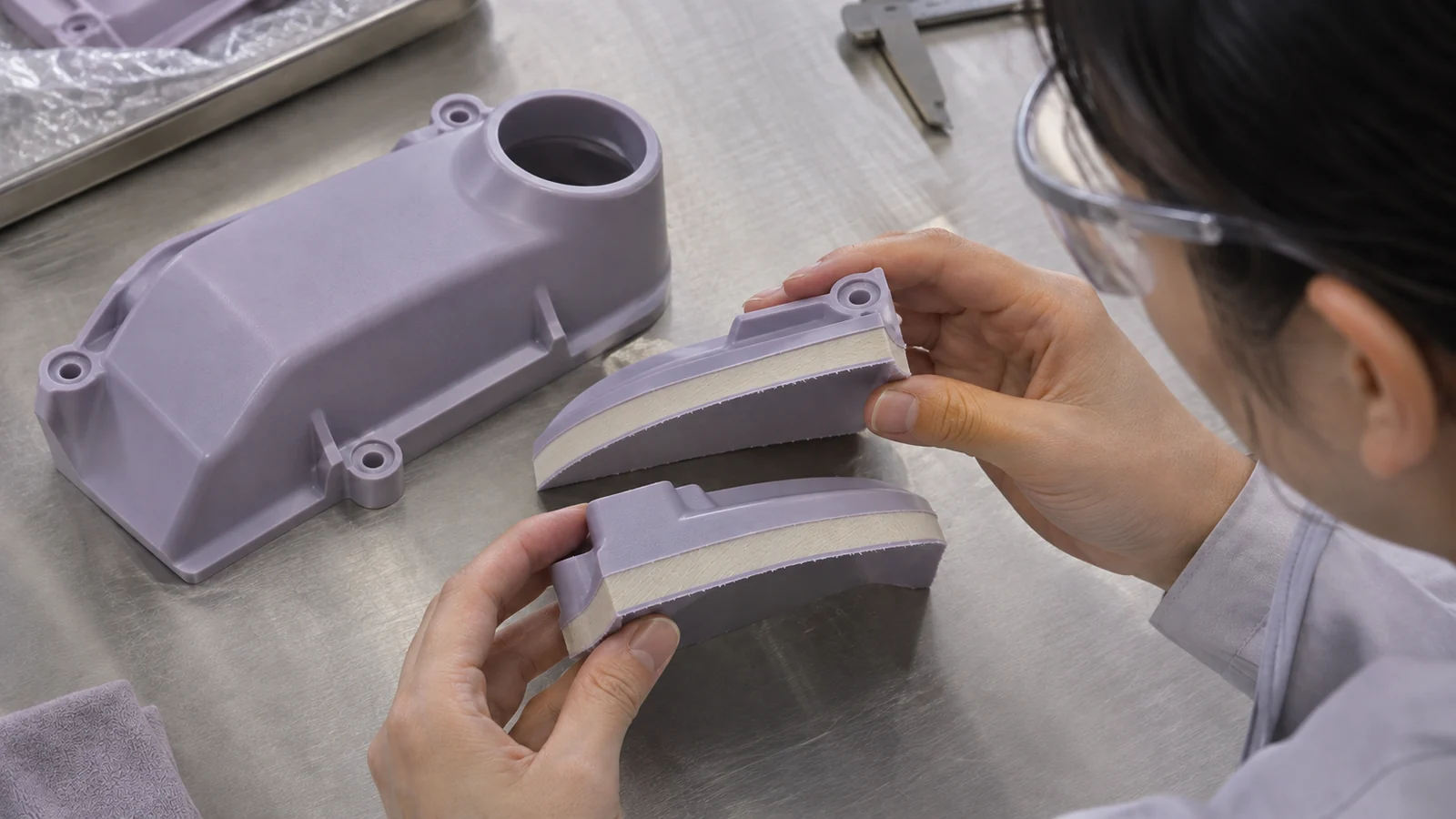
For critical boundaries, specify an acceptable interface location or exposure condition that can be checked on the molded part. This may involve a visual standard, sectioning of samples, or another agreed inspection method. Choose based on risk: a cosmetic housing and a structural component may need different proof.
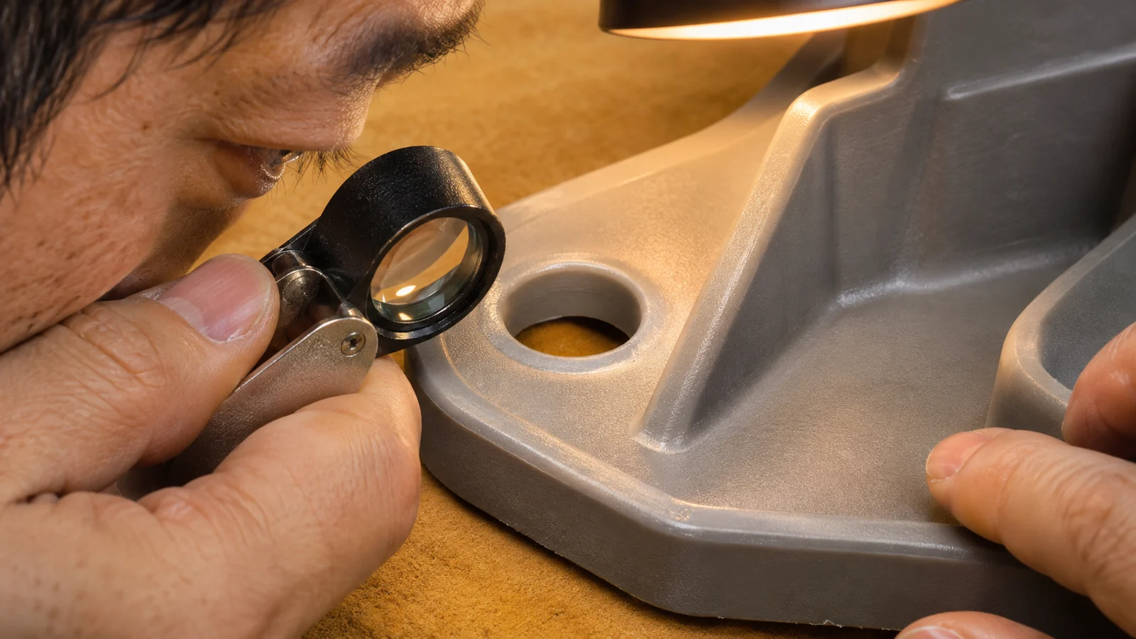
Plan transitions around holes, ribs, bosses, and thin sections. These features can redirect flow and make local coverage differ from a broad wall. A flat coupon may screen materials, but cannot establish how the skin behaves around real geometry.
3. Shape the part around the interface
Keep geometry legible to material flow and tooling. Abrupt thickness changes, narrow necks, isolated pockets, and long flow distances can complicate interface control. Where possible, use gradual transitions and avoid placing a critical boundary where geometry already creates a difficult flow condition.
Review ribs and bosses as part of the coverage map. If the core must remain hidden, confirm whether the requirement includes feature edges and sidewalls—not just the broad face. If the part needs a solid mount, specify how that region relates to skin and core. Verify the result with the actual tool and sequence.
Keep assembly and secondary operations in view. A screw, insert, weld, trim, or machined opening can expose the core after molding. Identify these operations early and decide whether the exposed boundary is acceptable.
4. Treat gate and flow strategy as design inputs
Gate location influences how materials enter and travel through the cavity. The preferred gate is not determined by appearance alone; consider fill distance, interface movement, weld lines, venting, and functional surfaces together. Moving a gate may improve one area while shifting a boundary elsewhere, so evaluate the whole path.
Before tool release, align on what the process must hold stable: material sequence, preparation, startup or purge procedure, and critical visual or functional outputs. Do not write a control plan around one nominal setting without establishing how the part responds to variation.
For process selection context, compare this design topic with two-shot versus co-injection molding. The choice changes design assumptions; the processes are not interchangeable routes for every two-material part.
5. Validate the actual skin-core boundary
Build validation around risk areas. Inspect show surfaces consistently, check assembly dimensions, and test the skin and core functions that matter in service. Where bond strength, sealing, chemical exposure, or impact matters, agree on a representative test rather than relying on appearance.
Sample locations that challenge coverage: flow-end regions, thin sections, around holes and bosses, and near transitions. Compare multiple shots from a stable run to distinguish a consistent boundary from a variable one. Tie revision, material identity, tool configuration, and process conditions to each sample.
The broader
plastic injection molding page is the L1 process reference. For adjacent commercial considerations, see how co-injection can affect material and packaging costs; verify cost assumptions against the actual part and requirements.
FAQ
Does the skin always fully surround the core?
That depends on design and process. Define required surfaces, permitted exposure, and how the boundary will be checked.
Can the skin-core interface be placed exactly at a CAD line?
CAD shows intent, but the molded interface depends on flow, geometry, materials, and process conditions. Verify it on representative parts.
Is material compatibility enough to prove the part will work?
No. Compatibility data is one input. Validate the interface for the actual geometry, service environment, and function.
What should be sent for an early co-injection design review?
Provide the 3D model, material roles and candidate grades, coverage map, visible zones, service conditions, assembly details, annual demand, and acceptance criteria.