
Good structural foam injection molding design begins by treating the part as two linked zones: a solid outer skin that meets the mold surface and a cellular core that reduces density through the interior. That structure can suit larger, thicker components, but it does not remove the need to design for flow, surface appearance, ejection, and assembly. The safest reviews make the skin requirements explicit before the tool concept is fixed.
Use the part’s function to decide where the skin must remain continuous, which surfaces can tolerate texture or process variation, and what dimensions must be verified after molding. This is the design conversation behind structural foam molding; the process should be selected around the part, not used as a shortcut for a geometry that has not been reviewed.
Start with the surface the customer will actually see
Structural foam parts can show a different surface character from a solid molded part. A drawing that labels every face “cosmetic” gives the tool team little useful direction. Divide the part into visible, functional, and non-critical zones, then specify what each zone must do: meet, seal, carry a load, accept a label, or remain out of sight.
For visible faces, review the expected texture, gloss, color, knit-line location, gate witness, and the effect of any later coating or assembly. Do not assume that a foam core will make every surface defect disappear. If sink appearance is the concern, compare the part’s geometry and the expected skin against the specific process route; the site’s existing microcellular foam discussion addresses that narrower issue.
Keep wall transitions deliberate
Large thickness jumps, isolated heavy bosses, and abrupt rib intersections can complicate fill and create uneven cooling behavior. A structural foam concept may make a thicker section feasible, but thick does not mean unconstrained. Use gradual transitions where the function allows them, connect ribs to walls without creating unnecessary mass, and avoid stacking several heavy features at one location.
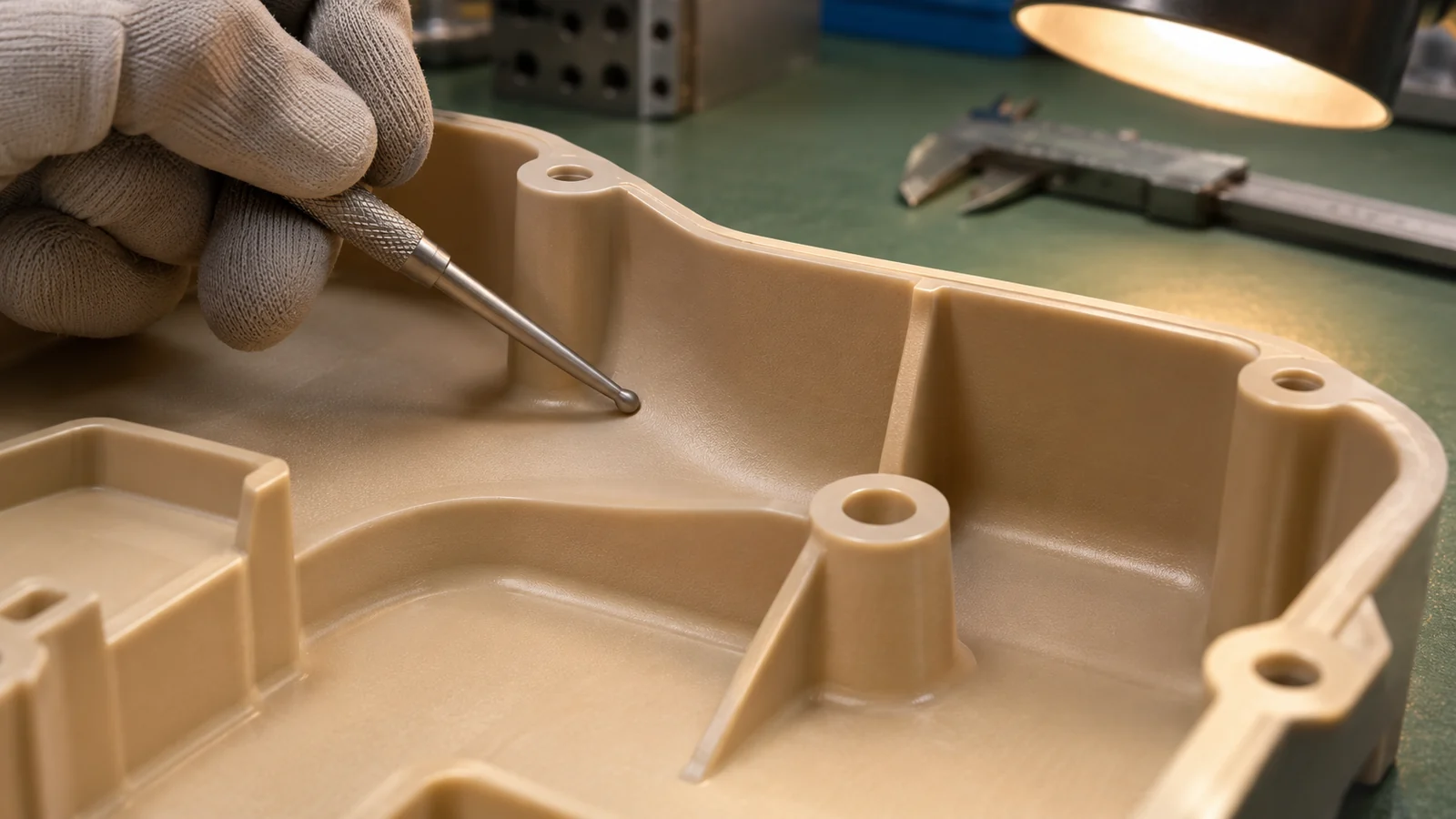
When a thick section cannot be removed, document why it is needed and how it is supported. Decide whether a ribbed section, a hollow feature, or a different process can meet the same load requirement with less material. This is a geometry decision, not a parameter-setting promise.
Design the flow path before choosing a gate location
Gate position affects where the melt enters, how the cavity fills, and where flow fronts meet. For a long or asymmetric part, a gate that looks convenient on the drawing may create a long path to a thin feature or place a visible mark on a face that must remain clean. Mark likely flow directions and potential meeting lines on the CAD review, then check whether those locations conflict with appearance, strength, or sealing requirements.

Vents also need a deliberate route for displaced air. End-of-fill areas, corners, and features that trap air deserve attention during mold design. The specific vent dimensions and gate details depend on the material, mold, and process design; they should not be copied as universal values from another part.
Plan ejection and measurement around the part’s warm state
A broad panel or enclosure may be flexible while warm, even if it is stiff enough after conditioning. Ejector locations, support surfaces, and any robot or operator handling should avoid distorting the part during release. Review access for ejection and consider where temporary support is needed between demolding and inspection.
Define the measurement state before tool release: the datum scheme, fixture or free-state method, time after molding, and the features that affect fit. Otherwise two teams can measure the same part under different support conditions and report different results. This principle also applies when the project uses a conventional injection mold design review—the inspection method belongs in the design plan.
A practical design review sequence
- Rank the surfaces. Mark cosmetic, sealing, mating, and non-critical areas.
- Explain every heavy section. Tie thick walls, bosses, and ribs to a load or assembly need.
- Trace the fill path. Review gate options, long flow paths, flow-front meetings, and end-of-fill zones.
- Review air escape and release. Identify venting needs, draft, ejector contact, and handling support.
- Set acceptance conditions. Define appearance limits, dimensions, measurement state, and sample approval responsibility.
Questions to resolve before the tool concept is locked
- Which faces are visible after assembly, and what surface variation is acceptable?
- Can a thick section be replaced by ribs or a different structural layout?
- Where can gate and flow-front marks appear without affecting fit or appearance?
- How will the part be supported and measured while its shape is still changing after ejection?
FAQ
Does structural foam automatically eliminate sink marks?
No. The result depends on part geometry, material, tool design, and process conditions. The design review should identify the heavy areas and define how appearance will be judged.
Can every surface be specified as cosmetic?
A project can set strict requirements, but the drawing should identify priority zones and measurable acceptance criteria. That helps the design and tooling teams assess trade-offs instead of treating every face identically.
Is structural foam the same as gas-assisted injection molding?
No. The processes create different internal structures and use different process strategies. Choose between them based on the part’s geometry, functional needs, appearance requirements, and validated tooling plan.