
Structural foam injection molding can be a good fit when a part needs a relatively stiff, thick-section structure without the mass of a fully solid molding. It is not automatically right for every large or ribbed component: visible skin, load path, cosmetic zone, and tooling plan all have to work together. These five checks help determine whether the process deserves a design study before the tool is committed. For buyers researching foam injection molding applications, the deciding factors are the part requirements and the production route.
Think of this as a part-level tradeoff, not a resin label. A cellular core can change weight and section behavior, while the mold-facing skin still carries appearance and surface requirements.
Quick answer: evaluate surface, load path, section transitions, production route, and validation as one system. If the part requires a flawless high-gloss face, thin uniform walls, or tightly controlled local dimensions everywhere, conventional solid molding or revised geometry may be simpler.
In this article:
- What surface quality must the part deliver?
- Where does the part carry load?
- Can the geometry support a foam core?
- Does the production route justify the process?
- What must be proven before release?
- FAQ
1. What surface quality must the part deliver?
Start with the face an end user sees, cleans, paints, or touches. Structural foam molding forms a skin against the mold around a cellular interior, but the skin is not a guarantee of a uniform high-gloss finish. Texture, flow, gas conditions, mold surface, and process stability influence what appears.
Map cosmetic zones before discussing the process. A hidden back face, textured enclosure, and high-gloss panel carry different acceptance risks. If a broad face is judged under directional light, state that requirement and review representative molded samples early. If texture is acceptable or the surface is hidden in assembly, the process may have more latitude.

- Define surfaces visible in the installed product.
- Specify gloss, texture, color, and allowable appearance variation separately.
- Identify surfaces later painted, coated, bonded, or covered.
Compare requirements with the structural foam molding process page, but tie acceptance to the finished component rather than a generic resin sample.
2. Where does the part carry load?
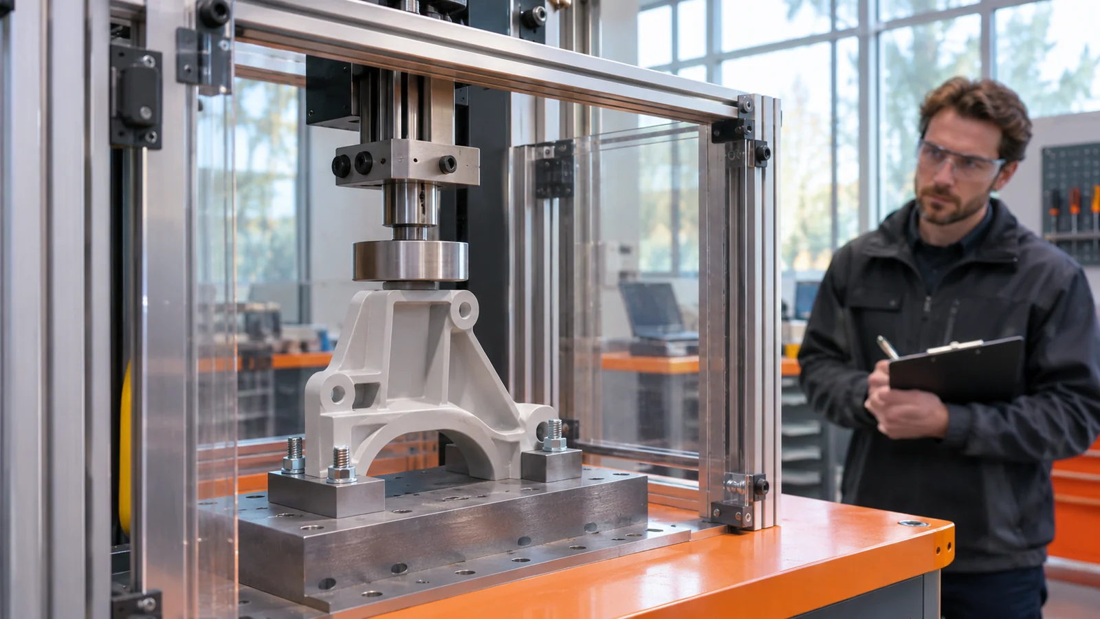
The process merits study when shape and section architecture can carry load efficiently. A thick panel with ribs, returns, bosses, and mounts may benefit from a lighter internal structure, but performance depends on how forces travel through the geometry. A screw boss, hinge, mounting point, or impact zone may require a solid region or additional feature.
Trace each load from attachment into the wall. Look for abrupt section changes, unsupported spans, and concentrated forces at corners. Reduced core material does not imply the same stiffness in every direction; bending, torsion, fastener pull-out, and impact are different cases.
For each critical load, record the failure mode that matters: excess deflection, cracking, boss damage, creep, or loss of fit. A simple enclosure panel and a component where local fracture creates a safety risk need different evidence and design margins.
3. Can the geometry support a foam core?
Review walls, ribs, corners, and flow length together. Abrupt thickness changes may complicate filling and contribute to appearance or dimensional variation. Long flow paths, isolated pockets, and poorly placed gates can make fill balance harder. Uniformity is not the only aim, but transitions should be deliberate and manufacturable.
Check that the geometry has room for the desired structure without compromising attachments or functional surfaces. Ribs and returns should serve the load path instead of merely adding bulk. Bosses may need local reinforcement; narrow passages, shutoffs, and vent locations require tooling review.
One early review method is to mark three zones on the CAD model: visible skin, primary load path, and local high-stress details. Discuss transitions between them with design and tooling engineering. If every feature relies on a highly controlled wall or pristine finish, reconsider geometry before process selection.
4. Does the production route justify the process?
Consider the full manufacturing route, not just the mold cycle. Value depends on expected volume, material use, tool complexity, secondary operations, inspection, and reject risk. A lower-mass molding may help an assembly, but it only matters if the system benefits and the part still passes requirements.
Compare options against the same drawing, appearance standard, load cases, and demand. Include implications for gates, vents, cooling, ejection, and post-molding handling. If the part needs cosmetic finishing or machining, include that work instead of assuming the molding route eliminates it.
| Review point | Why it matters | Evidence to gather |
|---|---|---|
| What does lower part mass change? | Part savings may not affect the full assembly. | Mass target and assembly-level impact |
| Which areas need solid response? | Mounts or loads may govern local design. | Load cases, attachment detail, prototype test |
| How sensitive is appearance? | Rejects can outweigh material savings. | Finish, lighting, approved sample |
| What changes in tooling or inspection? | Process needs a control and measurement plan. | Tool concept, inspection method, process study |
5. What must be proven before release?
Agree on success criteria before locking tooling. Identify surfaces to inspect, dimensions controlling assembly, load cases, and sample conditioning. Use representative part geometry and material; a coupon may answer one narrow material question but cannot prove the full component.
Stage the review: assess filling and appearance, check dimensions and ejection, then test in the intended assembly and service conditions. Keep settings and sample locations with the inspection record so one attractive sample is not mistaken for repeatable capability.
For adjacent cellular-core context, see microcellular foam injection molding. It is related, but the decision for a structural component still needs its own appearance, load, and tooling assessment.
FAQ
Is structural foam injection molding right for every large part?
No. Size alone is not decisive. Surface expectations, loads, geometry, material, and validation all matter.
Does the cellular core mean the molded skin is weak?
Not by definition. The skin and core have different roles, but actual properties depend on design and process. Test the part against requirements.
Can structural foam guarantee a smooth cosmetic finish?
No general process description can guarantee that. Define finish and inspection conditions, then verify representative molded parts.
What should be ready for a feasibility review?
Share the CAD model, drawing, material constraints, visible-zone map, loads, expected volume, assembly details, and acceptance criteria.