
Co-injection molding defects are easier to diagnose when you read the surface as evidence of how skin and core moved through the cavity. Core breakthrough, uneven skin coverage, a visible flow boundary, short fill, or inconsistent color can point to different parts of the filling sequence. The symptom alone rarely identifies the cause: gate design, material pairing, melt condition, timing, venting, and geometry can interact.
Document where the defect appears and whether it repeats in the same location. Compare parts from the beginning, middle, and end of a run, then relate the pattern to flow direction and the part’s functional surfaces. Make one controlled change at a time and check that the correction does not create a new defect elsewhere.
Fast diagnostic: map the defect, establish whether it is stable or intermittent, identify the skin/core boundary, and review sequence before changing settings. Do not treat every visible interface as a defect; acceptance depends on the drawing and surface criteria.
In this article:
- Map the defect before changing the process
- Core breakthrough or exposed core
- Uneven skin and visible interface
- Short fill, hesitation, and trapped gas
- Color inconsistency and contamination clues
- A controlled troubleshooting sequence
- FAQ
Map the defect before changing the process
Record the defect location on a part image or drawing. Note distance from gate, flow direction, nearby thickness changes, ribs, holes, and vents. Mark whether it occurs on a show surface, hidden surface, or functional interface. This makes observations comparable across shots and shifts instead of relying on memory.
Separate stable patterns from intermittent ones. A defect that repeats in one location may relate to geometry or flow balance; one that moves or appears sporadically may involve material preparation, machine sequence, or a changing condition. These are hypotheses, not diagnoses.
Capture the approved recipe and recent changes, including material lot, conditioning where specified, colorant, purge, startup, and maintenance. Confirm that compared parts came from the same tool and setup.
Core breakthrough or exposed core
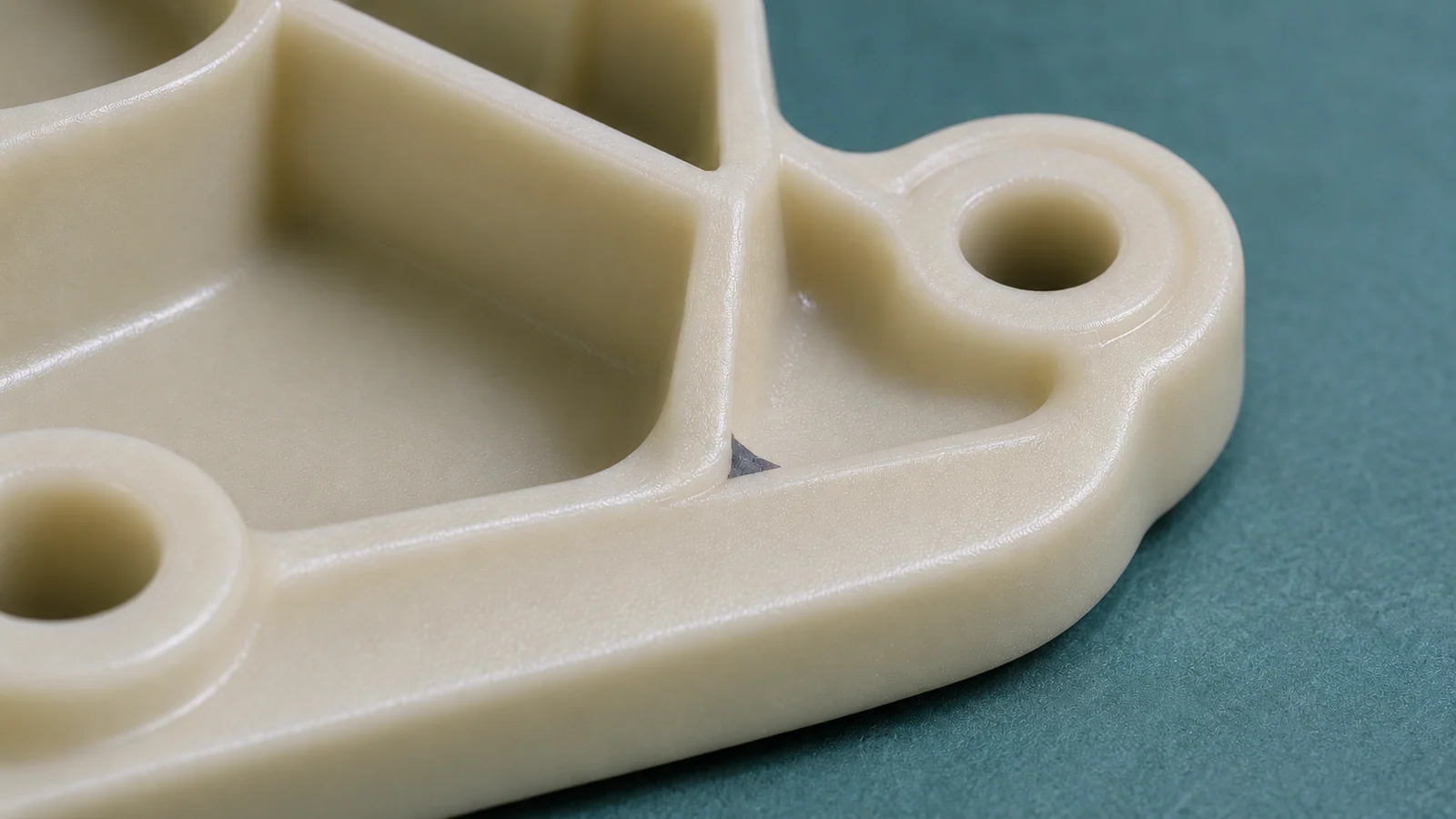
If the core appears where a continuous skin is required, identify whether exposure repeats at a flow-front location, a local thin section, or intermittently. Check the gate-to-feature path, wall transitions, sequence timing, and whether geometry creates a low-resistance route for the core. Review the part and tool rather than assuming one machine setting is responsible.
Confirm that intended materials were loaded and the sequence is stable. A material or color change can make a previously subtle interface more visible. If the defect occurs at a boss, rib intersection, or sharp transition, test a geometry or gate hypothesis alongside process checks; both can amplify one another.
Inspect more than the exposed spot before accepting an adjustment. A change that improves one surface may shift the interface or affect fill elsewhere. Record the location, affected shots, and boundary for acceptable exposure.
Uneven skin and visible interface
Skin thickness need not be uniform throughout complex geometry. If the surface shows streaks, a wandering boundary, or localized gloss or texture differences, map the pattern to flow length, wall thickness, corners, and section changes. Geometry can make the flow front behave differently across zones.
Confirm which visual changes are out of specification. A visible interface may be expected in a defined area but unacceptable on a customer-facing panel. Use approved samples and consistent lighting, distance, and viewing angle so inspectors classify parts consistently.
Review whether gate arrangement and filling sequence deliver intended coverage before focusing on finishing. Surface treatment may mask a symptom without correcting an unstable interface. For process-selection context, see two-shot versus co-injection molding; the methods should not be treated as interchangeable.
Short fill, hesitation, and trapped gas
Trace short shots and hesitation marks along the flow path. Look for thin sections, long travel, abrupt expansion, narrow gates, and features that divide and reunite flow. Inspect vents and parting-line conditions where gas could accumulate, but do not assume every incomplete fill is a venting problem.
Compare skin/core sequence with the incomplete area. If fill changes after a lot, startup, or setup adjustment, document that timing. Check material condition and recipe against the approved specification before changing setpoints. Where evidence points to geometry or gate restriction, engineering review may be more appropriate than a production-only adjustment.
Inspect both sides and neighboring features. Trapped gas may leave burn or discoloration; hesitation can leave a visible line. These clues narrow the investigation, but process records and functional tests are needed to confirm the cause and correction.
Color inconsistency and contamination clues
Color variation can result from material, colorant, purge, mixing, or the visual effect of different skin and core materials. Verify material identities and color concentrates, and review transition between runs. Determine whether variation follows flow, appears at startup, or changes shot to shot.
Distinguish a true color shift from a difference in gloss, texture, or skin coverage. Compare a consistent reference under agreed lighting and inspect the molded surface rather than relying only on phone photographs. Localized changes should be mapped to gate and flow; broad or intermittent changes call for review of material and setup history.
When materials differ, confirm that their roles and appearance criteria are documented. The relevant parent topic is plastic injection molding; co-injection must be assessed as a defined material and process arrangement, not a generic color effect.
A controlled troubleshooting sequence
- Contain and classify. Separate affected parts, identify defect type, and record location and frequency.
- Establish a baseline. Capture approved recipe, material identity, startup state, and recent tool or machine changes.
- Connect symptom to flow. Mark gate, flow direction, interface, section changes, and vents on the drawing.
- Test one hypothesis. Change one approved variable or inspect one design/tool feature; retain before-and-after samples.
- Confirm the whole part. Check appearance, dimensions, bond or function as applicable, and repeatability.
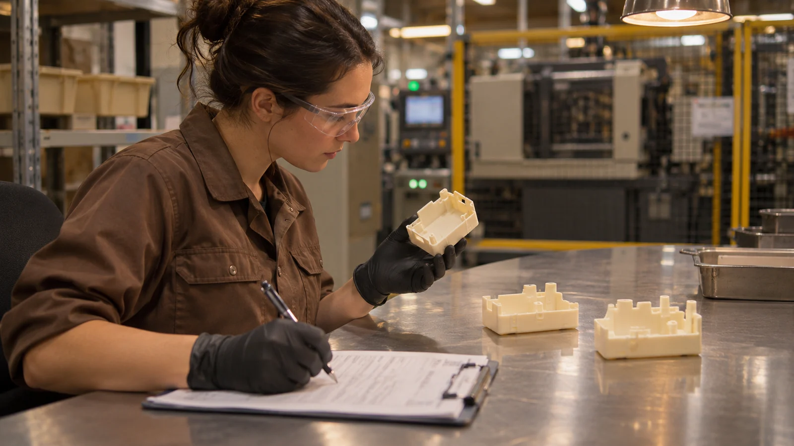
Keep a defect log with date, material lot, cavity, location, suspected cause, change, and result. This reduces repeated trial and error and helps separate startup issues from design or process-window problems.
FAQ
Is a visible skin-core boundary always a defect?
No. It is a defect only when it violates agreed appearance or functional criteria. Define acceptable location and visibility before production.
Should I increase injection speed to fix core breakthrough?
Not without evidence. The result depends on tool, materials, geometry, and sequence. Record a baseline and test one controlled, approved hypothesis.
Can a short shot be fixed only by changing process settings?
Not always. Material condition, gate and flow path, venting, geometry, and sequence may all matter. Diagnose location and repeatability first.
What information helps an engineering review?
Provide defect photos with marked locations, part and tool identification, material details, frequency, process records, and acceptance criteria.