
A molded bumper can protect a robot enclosure from scuffs and absorb some contact energy, but a soft surface alone does not make a mobile robot safe. Robot collision bumper overmolding is a design option when a rigid carrier needs a compliant contact layer; it must be evaluated alongside sensing, stopping behavior, mounting, and the robot’s hazard controls. The key decision is what the bumper is expected to do—and what it must never be mistaken for.
Define the bumper’s function—and its limits
“Bumper” can mean a cosmetic edge guard, a replaceable wear strip, a compliant contact surface, or part of a system that detects contact. Those functions should not be blended into one vague requirement. A cosmetic guard may be judged by appearance and scuff resistance. A compliant layer may need to avoid damaging the robot or nearby equipment during incidental contact. A sensing bumper has additional electrical, mechanical, and system-level requirements.
Write down contact locations, likely impact directions, object types, operating speed range, environmental exposure, and how the vehicle is expected to respond. If the bumper is part of a safety function, its performance must be assessed in the complete robot system under the applicable risk analysis and validation process. Overmolding by itself does not establish a safety rating or guarantee a safe stopping distance.
For the application context, the site’s robotics industry page covers molded components used around robotic systems. Here the focus is narrower: how a compliant skin and its rigid carrier behave together.
Choose a carrier-and-skin architecture that can be inspected
A rigid carrier can locate the bumper on the chassis and provide mounting features, while a softer molded layer creates the contact surface. The two materials may be joined by chemical adhesion, mechanical locks, or both. Select the interface strategy based on the exact substrate and elastomer grades, the expected loads, and how failure would appear during inspection.
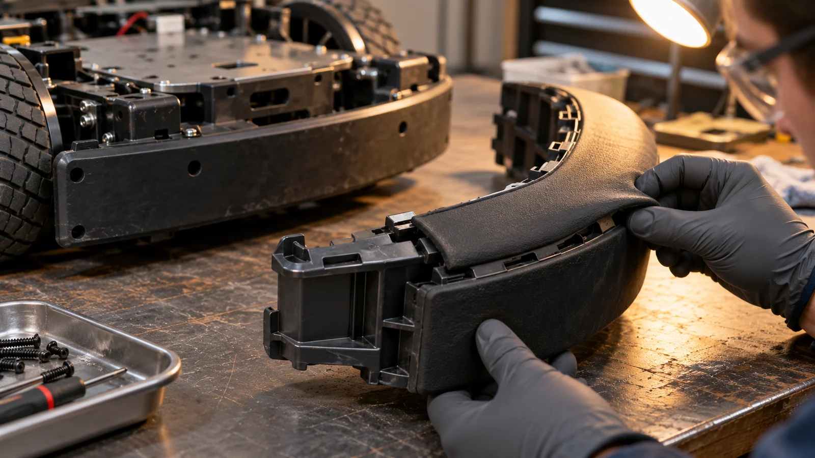
Do not rely on the assumption that a soft material will stay attached because it wraps around the carrier. Peel at the edge, rotation around the substrate, or separation after aging can expose a hard edge that the design intended to cover. Through-holes and undercuts can improve mechanical retention, but they affect mold filling, venting, material flow, ejection, and carrier strength. The appropriate geometry must be validated in the molded part.
Where a two-material route is being considered, review it as a complete overmolding design, including substrate location, shutoffs, interface preparation, and process repeatability. A mechanically assembled replaceable pad may be preferable when field replacement is a priority or when the material pair does not support a robust molded interface.
Shape the contact zone around the expected impact
A bumper’s thickness and profile influence how it deforms, but “make it thicker” is not a complete design rule. A broad flat face may spread contact over a larger area; a projecting lip may protect a seam but concentrate strain at its root. Corners, fastener openings, and abrupt thickness transitions can become tear initiation points, especially when the bumper is repeatedly compressed or scraped.
Review the bumper’s movement as well as its static shape. Check whether the soft layer can bottom out against the carrier, whether the carrier can contact the object first, and whether a compressed bumper can block a sensor or door. Include the mounting stiffness: a compliant skin on a flexible bracket may move farther than expected and create interference elsewhere.
- Mark the likely first-contact zones and directions on the CAD model.
- Keep the soft-to-rigid boundary away from the most peel-sensitive contact edge when feasible.
- Provide clearance for deformation without obstructing sensors, wheels, or service access.
- Design retention and inspection features so partial separation can be detected.
Keep sensing and compliance from fighting each other
Some robot bumpers work alongside proximity sensors, contact switches, or pressure-sensitive elements. The molded skin must not unintentionally shield the sensing path, preload a switch, pinch a wire, or change the trigger point as the material ages. If electronics are integrated into the assembly, define connector routing and strain relief before the mold layout is finalized.
Separate physical protection from detection logic in the requirements. A compliant bumper may reduce surface damage during light contact, but it cannot replace the sensing, control, braking, or risk-reduction measures required by the robot’s system design. Verify the complete assembly in the actual mounting position, including the sensor’s field of view and the robot’s response to contact.
Test the installed bumper, not just a material sample
Material coupons can help compare candidates, but they do not reproduce the carrier interface, molded edge geometry, fasteners, or installed deformation. Validate representative molded assemblies with the actual mounting method. Define contact energy or force conditions through the system’s engineering and safety process, then observe deformation, rebound, attachment, sensor response, and any contact between the carrier and the external object.
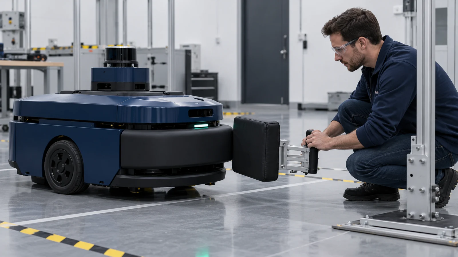
Age and environment matter. Temperature, cleaning chemicals, oils, UV exposure, and repeated compression can change a polymer’s behavior. Use the exposures that match the robot’s service environment, and repeat relevant contact and sensor checks afterward. Inspection criteria should identify edge lift, cracks, permanent set, loosened fasteners, and changes in switching behavior.
| Validation item | What it reveals | Check after conditioning? |
|---|---|---|
| Interface retention | Peel, rotation, or local separation | Yes, after relevant aging and cycling |
| Contact deformation | Bottoming-out or hard-carrier exposure | Yes, at representative temperature |
| Sensor response | Blocked path, preload, or changed trigger | Yes, before and after service cycling |
| Mounting durability | Fastener loosening or bracket movement | Yes, after vibration or repeated contact |
What engineering should specify before tooling
Share the carrier and bumper CAD, exact candidate materials if known, mounting details, expected contact zones, robot speed and operating environment, cleaning exposure, required sensor behavior, annual quantity, and service or replacement strategy. Identify whether the part is a cosmetic guard, a wear component, a compliant interface, or a component in a safety-related function.
That distinction drives the geometry, material screening, mold interface, inspection plan, and validation scope. If the acceptance criteria are still undecided, begin by defining the system-level contact scenarios rather than asking a molder to select a material based only on “softness.”
Questions buyers ask
Does a soft overmolded bumper make a mobile robot safer?
Not by itself. It may protect surfaces or provide compliance, but system safety depends on the robot’s sensing, controls, stopping response, use environment, and validated risk-reduction measures.
Should the bumper be permanently molded onto the carrier?
Permanent overmolding can reduce separate assembly steps when the material interface and service life are suitable. A replaceable pad may be better when wear is expected, field repair matters, or the material pairing cannot be validated for a durable bond.
Can the bumper include a contact sensor?
Potentially, but the sensor, wiring, molded skin, and control response must be engineered and tested as one assembly. The overmold must not preload, obstruct, or isolate the sensing element in a way that changes its intended response.