
Robot cable management clips injection molding is a part-design problem, not simply a way to make a cable holder lighter. The clip must retain the harness during motion while avoiding pinch, abrasion, and a bend tighter than the cable allows. A design that holds the cable firmly on a static bench may still loosen, creep, or wear through the jacket after repeated robot travel. Begin with the route and the cable’s motion envelope, then size the retention feature around those constraints.
Map the route before drawing the clip
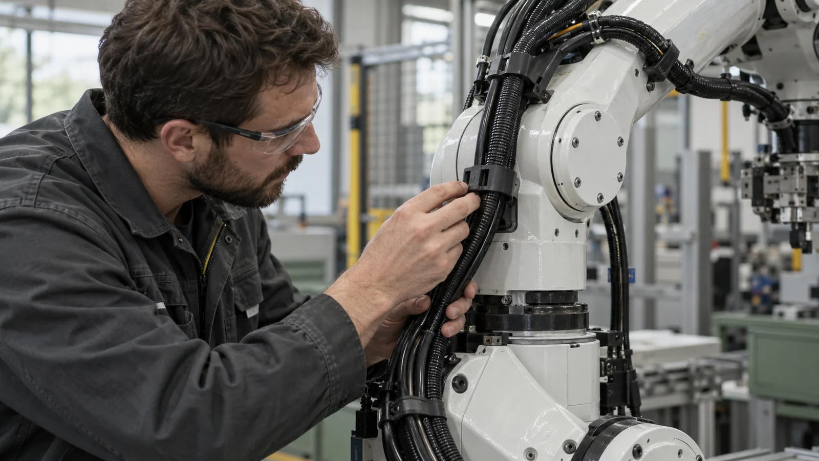
A cable clip controls a local point; the robot route controls the system. Map cable movement through every relevant arm position, including wrist rotation, tool changes, and service access. Mark fixed points, moving spans, abrasion surfaces, and areas where the harness approaches a joint or sharp enclosure edge.
Use the cable supplier’s dynamic bend and torsion limits as inputs. A clip should not force the harness into a smaller radius just because the part fits the available space. If the route requires a tight turn, adding clips may lock the cable in place and shift bending stress to the next unsupported span.
At the assembly level, a robotics application review should include cable motion alongside the molded component. This is different from a molded boot at the cable exit: a clip guides or retains a route segment, while an overmolded transition protects a local termination.
Choose retention without crushing the jacket
Retention should prevent unwanted migration without turning the clip into a clamp. The needed grip depends on cable diameter variation, jacket material, vibration, movement, and installation method. Provide enough opening and lead-in for assembly, but avoid edges that scrape the jacket as the cable is inserted or serviced.
Clip geometry can be tuned through the opening, return lip, contact length, and support beneath the cable. A very tight snap may be difficult to assemble and may cut into a soft jacket; a loose clip may allow repeated impact or rubbing. Review tolerance stack-up between the molded clip, cable diameter, mounting surface, and fastener location rather than specifying the clip in isolation.
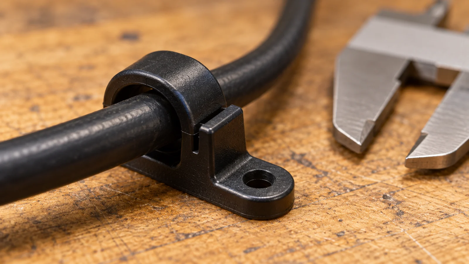
Where the cable must move within the holder, the clip should guide without blocking that motion. Where it must stay fixed, use a retention concept intended for that function and validate the jacket’s compression response. These are different design conditions and should not share one unexamined geometry.
Design for repeated service and motion
A robot harness sees cycles that can combine bend, torsion, vibration, and contact with nearby hardware. The clip may remain intact while the cable jacket wears underneath it. Conversely, the clip’s snap arm may fatigue or creep and gradually lose retention. Inspect both the molded component and the cable after representative cycling.
Serviceability matters too. If technicians must remove the cable during maintenance, an overly aggressive latch can damage the jacket or break during removal. If the clip is disposable or not intended to be reopened, make the service procedure clear and ensure access for the fastener or mounting feature.
Material choice depends on the clip’s strain, temperature, chemical exposure, and expected replacement interval. A flexible resin may help with snap assembly but may not preserve the same holding force under sustained deflection. A stiffer resin may retain shape but raise insertion force or create a sharper contact. Evaluate the actual grade and molded geometry together; the engineering plastics range is a starting point, not a substitute for part testing.
Check the clip as a molded part
Snap features are sensitive to wall thickness, root radius, flow direction, and ejection. A thin latch can short-shot or warp; a thick base may cool differently from its arms. Keep the clip’s functional opening and mounting face tied to practical datums so inspection can confirm the dimensions that control retention.
Place the gate and parting line away from the most highly strained latch root when possible. A weld line or flash at a snap feature can change assembly force or become a crack starter. Also check draft and ejection direction: a clip that releases cleanly from the mold is more likely to keep its intended geometry than one that must be forced off a core.
For a plastic injection molding review, provide the cable and mating assembly, installation sequence, required retention behavior, service environment, and any cable-vendor limits. If the clip is part of a larger harness design, clarify which components are being molded and which are supplied separately.
Verify the harness in its installed path
Do not approve a clip from a single insertion test. Check assembly effort, retention, cable movement, and wear in the installed robot route. The most useful test includes the cable, clip, mounting surface, fastener, adjacent links, and representative motion.
- Fit check: confirm the cable seats without jacket damage or excessive force.
- Retention check: verify the cable stays where intended under the expected movement and vibration.
- Clearance check: cycle the robot through the required envelope and inspect nearby contact points.
- Wear check: inspect jacket and clip after representative operation for polishing, cuts, cracks, or latch set.
- Service check: remove and reinstall the cable using the real maintenance procedure.
| Design choice | Potential benefit | Risk to validate |
|---|---|---|
| Tight snap opening | Strong initial retention | High insertion force or jacket damage |
| Longer contact surface | More distributed support | Restricted cable movement or service access |
| Flexible latch arm | Easier installation or removal | Creep, fatigue, and retention loss |
FAQ
Should a robot cable clip stop all cable movement?
No. Some locations need fixed retention; others need controlled movement. Define which span is fixed and which must flex, then place clips so the cable does not transfer bending stress to an unintended point.
Can a molded clip define the cable’s minimum bend radius?
Not by itself. The full route, cable construction, robot motion, and supplier limits determine the bend condition. The clip should preserve the required path rather than forcing an arbitrary radius.
What should be sent for clip DFM?
Provide the clip CAD, cable diameter and jacket specification, installed route, mounting surface, service method, motion envelope, environment, and the retention or wear criteria that matter.