
Robot cable overmolding is most useful at a defined termination or transition—not across the section that must flex and twist through the robot’s motion. A larger molded boot does not automatically reduce cable failures. If it moves the bend point to a short, stiff boundary, the conductor or jacket may still fatigue where the flexible cable exits the overmold. Start by locating the real failure zone and mapping the motion before changing the molded geometry.
Read the failure location first
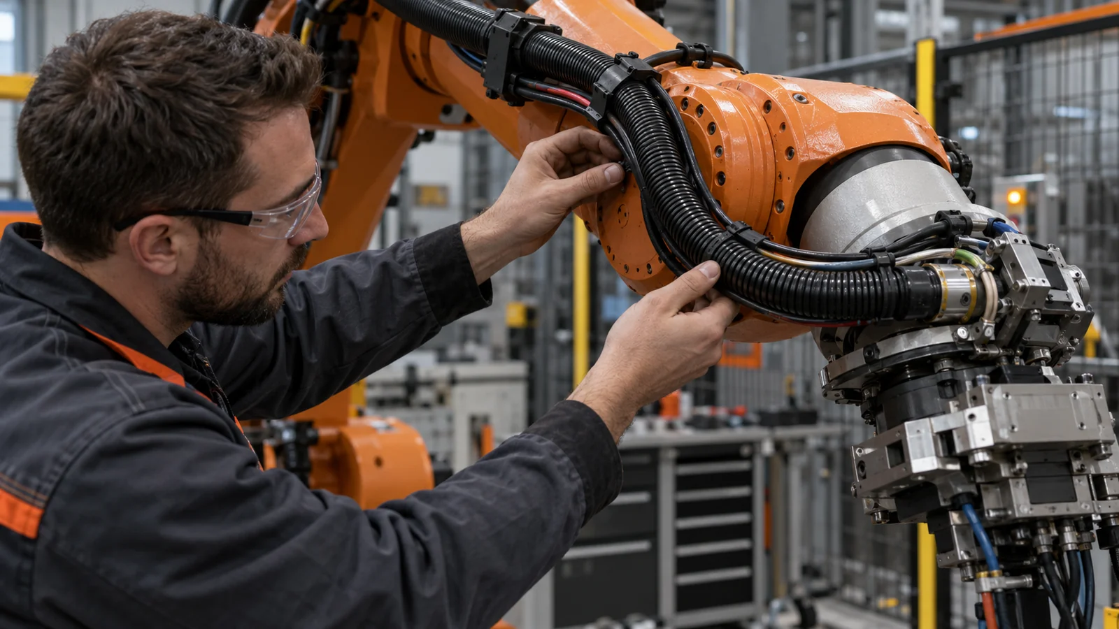
Before redesigning a boot, inspect where the cable fails and how it was installed. A conductor break near the termination, a split in the outer jacket, a pulled connector, and abrasion farther along the arm point to different causes. Record the robot axis, cable path, bend direction, torsion, clamp positions, and whether the failure follows a particular motion or tool orientation.
The molded transition should address the load it actually sees. It may help protect a termination from handling or reduce an abrupt change in support, but it cannot correct an unsuitable cable, excessive travel, collision, or a routing path that repeatedly twists the same segment. Keep cable manufacturer limits for bend and torsion as design inputs; do not infer a universal bend radius from the molded part alone.
Within a robotics injection molding project, scope cable overmolding as a molded component around an identified cable or connector interface. It does not imply that the molding supplier provides the complete cable harness, conductor termination, electrical test, or robot dress-pack system unless those services are separately confirmed.
Keep the moving cable out of the rigid boundary
The most sensitive region is often the point where a flexible cable leaves a stiff molded boot. If that boundary sits directly at a repeated bend or twist, the transition can concentrate strain instead of distributing it. Draw the cable’s full motion envelope and mark where it is clamped, where it can move, and where it must remain protected.
Use the overmold to support the termination without gripping the cable so aggressively that it creates a new stress concentration. A gradual transition may reduce abrupt stiffness changes, but the right length and shape depend on cable construction, jacket material, motion, and surrounding clearance. Confirm the cable can move through the required path without rubbing against the robot link, cover, or neighboring cables.
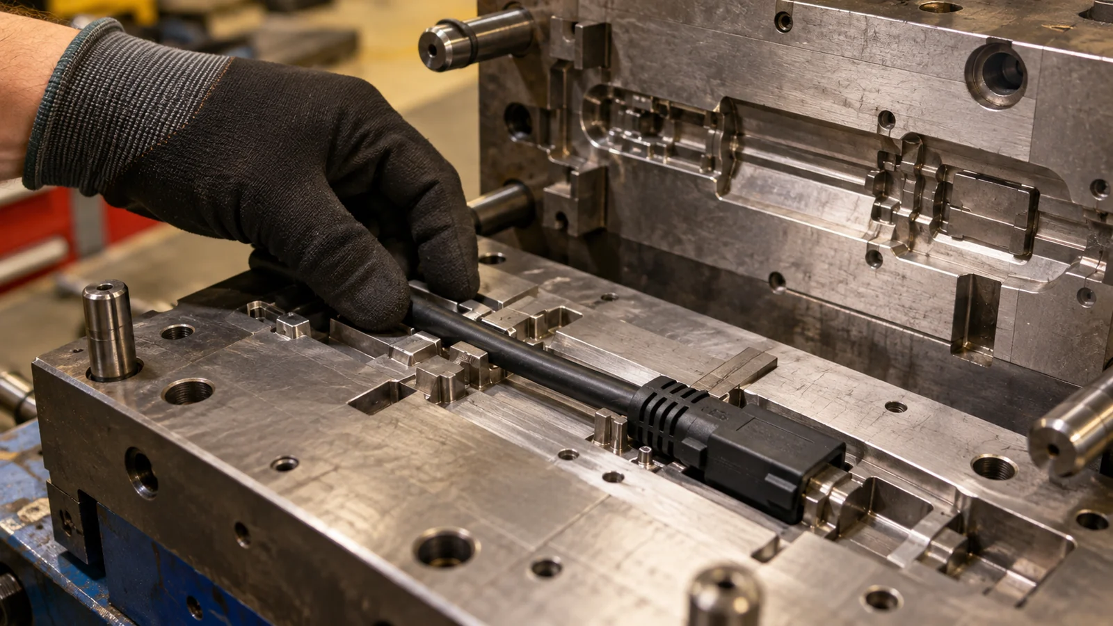
For the insert-molding step, check whether the cable jacket tolerates the molding temperature, pressure, and resin contact. Shielding, connector geometry, cable position, and any required electrical isolation need to be understood before the tool is finalized. If the design includes a metal terminal or other insert, review the applicable insert injection molding considerations alongside the overmold.
Design the molded transition around the cable
Retention can come from adhesion, molded geometry, or a combination, but it must match the cable jacket and termination. Do not assume the overmold will chemically bond to every jacket. A mechanical stop, connector shoulder, or captured feature may be needed to resist pullout, while a poorly placed sharp edge can damage the jacket during flex.
Define the cable’s position in the mold with stable locating features that do not crush or distort it. The shutoff must control flash without cutting into the jacket. Consider how trapped air escapes around the insert and how the cable can be loaded and removed without disturbing the critical position. A repeatable process depends on the cable being presented consistently, not merely on a cavity that looks right in CAD.
Specify the resin and cable construction together. Compatibility, temperature exposure, flexibility, chemical contact, and required color or identification all affect the choice. Material and geometry should be reviewed as one interface; the label “strain relief” is not a performance specification.
Test the complete routed assembly
A pull test can reveal retention weakness, but it does not represent robot motion. Validation should use the intended cable, connector, molded transition, routing hardware, and motion sequence. A boot that passes an axial pull may still fail under repeated flex at the transition.
- Document the baseline: photograph routing and mark the observed failure location.
- Check installation: confirm connector seating, cable clamps, and available slack.
- Run representative motion: include the robot axes and tool orientations that create bending or torsion.
- Inspect after cycling: look for jacket whitening, cracks, pullout, abrasion, or conductor continuity changes.
- Repeat after service exposure: add the actual temperature, cleaner, oil, or handling condition if it is part of use.
Set acceptance criteria before the test: what counts as jacket damage, allowable movement at the termination, and whether continuity or signal performance is measured. A passing appearance check alone cannot confirm electrical integrity.
| Observed issue | First area to inspect | Evidence to collect |
|---|---|---|
| Break near molded exit | Stiffness transition and repeated bend point | Motion path and flex location |
| Boot moves on cable | Jacket compatibility and retention geometry | Pull test and post-cycle movement |
| Jacket scuffs farther down route | Clearance, clamp position, and rubbing surface | Full assembly route and wear marks |
Know when a separate guide is better
Overmolding is appropriate when the termination needs an integrated protective transition. It is not the same as routing a moving cable along the arm. A separate clip or carrier can control the path and maintain clearance, while a molded boot protects only the local exit. Some designs need both; others need a different cable or routing strategy before a molded feature is considered.
For a molding review, provide cable and jacket specifications, connector drawings, the required movement, installation sequence, environment, and observed failure evidence. That is more useful than asking for a generic “stronger strain relief.”
FAQ
Can overmolding stop a robot cable from breaking?
It may improve support at a termination, but it cannot solve every fatigue cause. Identify whether the break comes from bending, torsion, abrasion, pullout, or an unsuitable cable and validate the full route.
Will the molded resin bond to the cable jacket?
Not necessarily. Adhesion depends on the exact jacket and molding material. Confirm compatibility and use mechanical retention when the interface requires it.
Should the boot cover the cable’s moving section?
Usually the design should preserve the cable’s required flexibility rather than immobilize the active bend zone. Map the motion and follow the cable supplier’s limits before defining the molded boundary.