
Injection molded robot end effector parts can work when the component’s geometry, load path, and service conditions fit the selected resin and tooling route. The decision is not “plastic or metal” in the abstract. A camera shroud, cable guide, sensor bracket, gripper finger, and tool-change cover carry different loads and have different consequences when they flex or wear. Classify the part by function first, then identify which dimensions and interfaces must remain stable during the robot’s actual motion.
Separate the end effector into functional parts
An end effector is an assembly, not a single material choice. Its parts may include a structural plate, finger, protective cover, sensor mount, cable guide, or contact pad. Some are mostly cosmetic; others locate a tool or react to acceleration and gripping force. If the whole assembly is evaluated as one undifferentiated “robot hand,” a low-risk cover can dominate the review while a small locating feature receives too little attention.
Make a simple function map: what the component touches, what it locates, what it protects, and what load it transfers. Mark any feature that affects tool center point, sensor field of view, repeatable pickup, or clearance with nearby equipment. Those are the features to protect in the mold and inspection plan.
The site’s robotics injection molding page is the application-level entry point. A component-level review should narrow the discussion to the actual end-effector function, assembly, and failure consequence rather than repeat a general overview of robotics.
Map the load path before changing material
Trace force from the workpiece through the finger or tool, through fasteners and brackets, and back into the robot flange. Then include acceleration and stopping: a part may be lightly loaded while gripping but see a different force when the arm changes direction. If the load path crosses thin walls, long cantilevers, or a boss with limited support, simply switching to a stronger-sounding resin may not solve the design problem.
For molded parts, wall transitions, ribs, bosses, and openings determine how material is distributed and how the part cools. Uneven sections can increase differential shrinkage or distortion, which may move mounting faces or sensor datums. Keep ribs connected to load-bearing walls, avoid abrupt thickness jumps where possible, and review the parting line and gate location against the surfaces that must stay accurate.
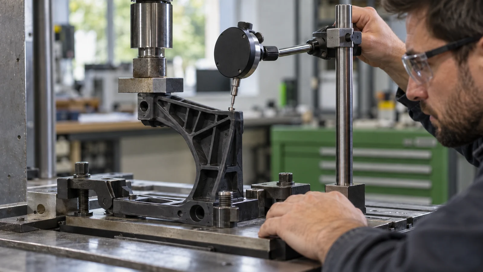
Material selection should reflect temperature, chemical exposure, impact, stiffness, creep under sustained load, and wear. The engineering plastics selection is not a substitute for a grade-level review: reinforcement, conditioning, orientation, and geometry can all change finished-part behavior.
Protect datums, fasteners, and sensor alignment
Robot tooling often depends on a few small interfaces more than on the outside shape. A molded bracket may fit the flange but still shift a sensor if the locating scheme relies on screw clearance alone. Define primary datums, fastening sequence, and the direction in which the assembly is expected to seat. If a metal insert is used, specify its position and rotation relative to those datums; do not assume the insert will remain perfectly located without a controlled mold design and inspection method.
Fastener bosses need enough surrounding material to resist the assembly load without creating a sink mark or a thin cosmetic wall. For repeated service, consider whether threads, inserts, or a replaceable wear component make more sense. Each choice changes tooling, assembly, and repair requirements, so decide before the prototype geometry becomes frozen.
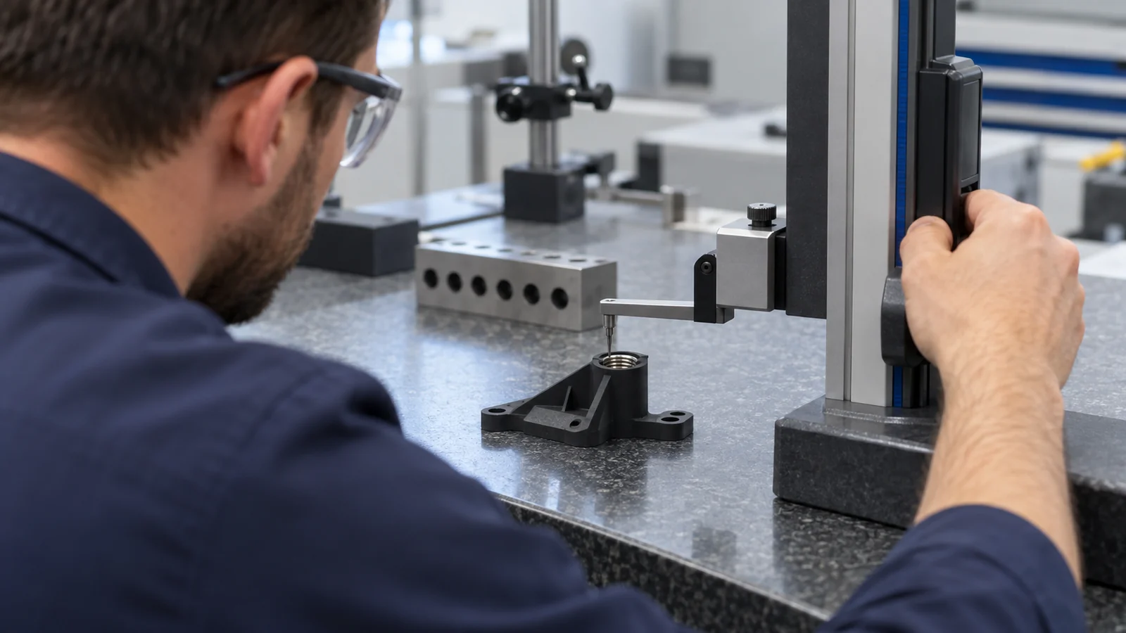
Where the design includes electrical or sensing hardware, protect connector access and cable exit paths as part of the molded-part envelope. The plastic should locate and protect components without pinching wires or making maintenance unnecessarily difficult.
Use molded geometry deliberately
Injection molding rewards geometry that fills, packs, cools, and releases predictably. Draft, ribs, gussets, and local thickness should support the functional load path while allowing the part to eject without damage. A sharp internal corner at a highly loaded root can concentrate stress; an overly thick boss can create a cooling and appearance problem. Neither issue is solved by adding material everywhere.
When metal-to-plastic integration is needed, distinguish a structural insert from a decorative or locating insert. The insert can carry a thread or bearing surface, but the surrounding polymer still needs enough length and geometry to resist pullout, rotation, and local cracking. If the insert is electrically active or connected to a sensor, define insulation and isolation requirements separately from mechanical retention.
For a custom plastic injection molding review, send the assembly model where possible, not only the isolated part. Neighboring components reveal cable paths, collision envelopes, and the actual datum chain.
Validate the task, not just the drawing
Dimensional inspection confirms measured features at one time and condition. It does not prove the end effector will maintain position through a working cycle. Validation should link the drawing’s critical features to the robot task and the consequences of variation.
- Define the task envelope: payload, acceleration, orientation, cycle frequency, environment, and maintenance interval.
- Identify critical interfaces: flange datums, tool center point, sensor position, cable exits, and clearance surfaces.
- Inspect representative molded parts: include the features whose movement could change grip or sensing.
- Run functional trials: measure repeatability, slip, collision, and change after temperature or chemical exposure where relevant.
- Review failure evidence: distinguish molded-part deformation from fastener loosening, wear, and robot-program changes.
Do not claim a load rating from a CAD model alone. The conclusion depends on resin grade, fiber orientation if reinforced, geometry, assembly, temperature, and cycle history. When those inputs are not fixed, treat the result as a design hypothesis to verify.
| Part function | Priority to control | Useful validation evidence |
|---|---|---|
| Structural finger or bracket | Deflection, root stress, fastener retention | Functional load and cycle test |
| Sensor or camera mount | Datum position, vibration, field of view | Alignment check before and after motion |
| Protective cover or cable guide | Clearance, impact, cable wear, service access | Collision and routing review in the full assembly |
FAQ
Can every robot end-effector part be molded in plastic?
No. The part must meet its structural, thermal, wear, and precision requirements in the chosen grade and geometry. Highly loaded interfaces may need inserts or another construction.
Should I send only the component CAD?
Send the component and, when available, the neighboring assembly. The full context helps assess datums, cables, tool access, collision clearance, and how the part transfers load.
What matters most when replacing a metal end-effector part?
Start with the actual load path, stiffness requirement, mounting datums, temperature, and motion cycle. Compare finished-part behavior—not material datasheets alone—and validate the molded design in the robot task.