
Low-pressure molding process parameters are grade-, tool-, and assembly-specific. The settings must fill the cavity and protect the electronics while producing the required coverage, boundary, and bond. There is no universal temperature or pressure recipe that applies to every hot-melt grade and assembly. Begin with the material supplier’s current processing guidance, then establish a controlled window using representative parts and defined acceptance checks.
Which variables matter together
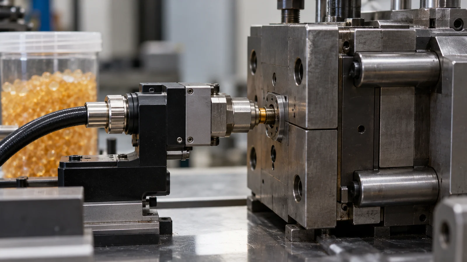
Material temperature and viscosity influence flow, but the resulting fill also depends on injection pressure or force, flow rate, cavity geometry, gate, venting, and assembly position. Mold temperature and cooling or hold time affect how the material solidifies and when the component can be removed. These variables interact; changing one can alter coverage, flash, component movement, or the final interface.
| Variable group | What to observe |
|---|---|
| Material preparation | Grade, lot, storage, conditioning, and compliance with supplier handling instructions |
| Material delivery | Actual temperature and flow behavior, pressure response, and fill sequence |
| Tool and assembly | Gate, vent, shutoff, locating, cable routing, and any component movement |
| Solidification and release | Coverage stability, flash, distortion, adhesion condition, and safe demolding |
| Verification | Dimensional, visual, functional, or environmental checks required for the product |
Use the supplier’s data for the exact material grade. Do not transfer a setting from another polyamide or polyolefin hot melt merely because the resin family appears similar. A different formulation, tool, or assembly can require a different validated setup.
Build the first trial from documented inputs
Before molding, record the material manufacturer and grade, lot, storage or conditioning history, assembly revision, tool revision, machine, and current process values. Confirm that the assembly is loaded consistently and that the intended keep-out areas are clear. Capture a baseline sample and define what the team will inspect.
For delicate components, identify the allowable movement or damage criteria before the trial. For coverage or adhesion, define the inspection method and test condition. If the acceptance rule is not measurable, the team cannot reliably decide whether one parameter change helped.
Adjust settings without hiding the cause
- Start within the supplier’s documented processing guidance and the approved safety limits.
- Change one variable or one planned group at a time, noting the reason and expected response.
- Keep material, assembly placement, and tool condition controlled during the comparison.
- Inspect coverage, boundary, flash, component position, and bond—not just whether the cavity filled.
- Repeat promising conditions and confirm they do not create new defects on another feature or sample.
If fill is incomplete, first examine the flow path, gate, venting, material state, and assembly location; increasing pressure without checking component limits can create damage or flash. If flash appears, inspect shutoffs and assembly variation before reducing every other setting. Parameter changes should address evidence rather than compensate blindly for a design issue.
Define what a successful setting looks like
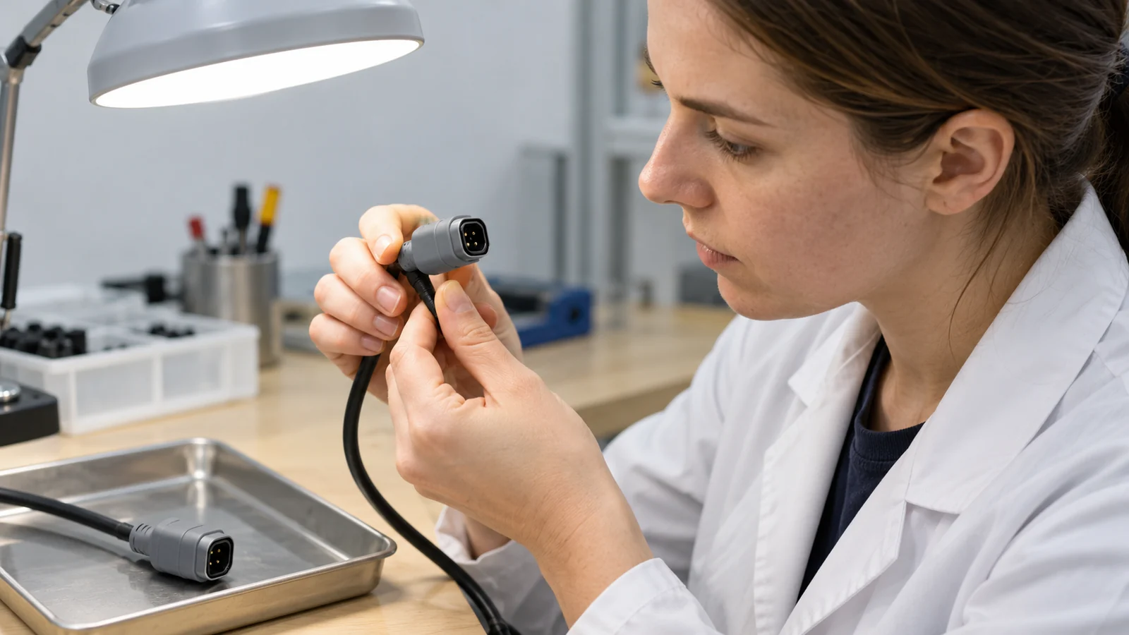
A production setting is not qualified because one part looks acceptable. Define the required coverage and boundary, verify that connectors and wires remain in position, confirm adhesion or sealing when applicable, and complete any electrical, environmental, or mechanical checks required by the product. Keep the samples linked to their material, tool, and process records.
Record the validated settings and the conditions that could change them, including material lot, startup, assembly variation, or tool maintenance. Establish response actions for drift instead of relying on an undocumented “good operator setting.” For the process overview, see low-pressure molding for electronics protection.
FAQ
What is the correct injection pressure for low-pressure molding?
It depends on the exact grade, tool, and assembly. Use the supplier’s current processing guidance and validate settings against component limits and part acceptance criteria.
Should temperature be increased when the material does not fill?
Not automatically. Check material handling, gate and vent design, assembly location, and the supplier’s instructions. A temperature change may affect adhesion, flow, flash, or component exposure.
How many parameters should change in one trial?
Change as few as the study needs to answer a clear question. If several settings move together, it becomes harder to identify what caused the result.