
An AGV body panel is not just a cover: it may protect wiring, provide service access, carry labels or sensors, and take occasional contact from carts or fixtures. AGV body panel injection molding is worth evaluating when the part geometry, expected volume, and cosmetic requirements justify dedicated tooling. It is not automatically the best route for every large shell; panel size, stiffness, impact exposure, and how the vehicle is assembled should decide the architecture.
Define the panel’s job before choosing its process
Start by separating structural duties from enclosure duties. A skin that hides internal components can often use ribs, returns, and discrete fasteners to achieve stiffness without carrying the vehicle’s primary loads. A panel that supports a sensor, bumper, battery restraint, or lifting point has a different job and needs its load path defined before the mold is designed.
Map the interfaces that the panel must preserve: chassis datums, door gaps, sensor fields of view, wheel clearance, connector access, and any surfaces that operators touch. This prevents a common mistake—optimizing the visible outer surface while leaving the hidden bosses or clips too flexible to hold alignment through repeated service.
For the broader manufacturing context, the site’s robotics injection molding overview identifies the application area; the part-specific decision still depends on the vehicle’s layout and operating conditions.
Why large, shallow panels are hard to keep straight
Large panels combine long flow paths with broad, relatively thin walls. If the wall, rib, and boss layout is unbalanced, differential cooling and shrinkage can pull the part out of plane. A panel may look acceptable on a bench but rock on the chassis, open a seam, or shift a sensor after fasteners are tightened.
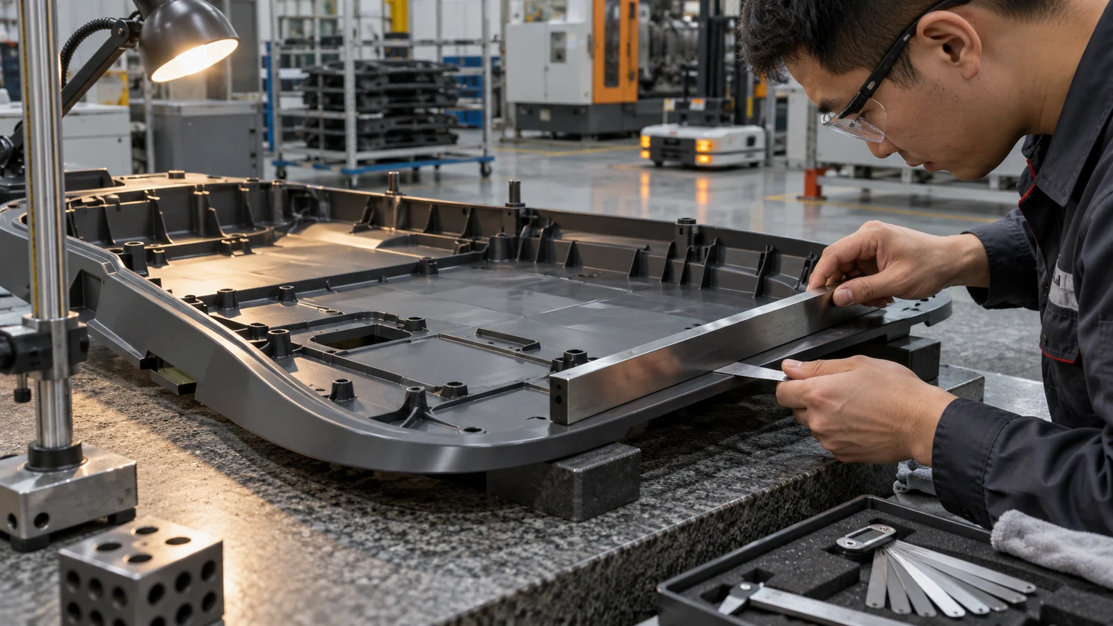
Do not treat nominal wall thickness as the only control. Rib height and thickness, transitions around bosses, gate location, material flow direction, cooling layout, and the order in which the panel is restrained all affect the result. Heavy ribs added late can create sink or local stiffness changes; a thick boss attached abruptly to a thin skin can become a stress and distortion source.
- Keep ribs and returns purposeful: use them to support spans and fastener zones, not to thicken the whole panel.
- Use gradual transitions around bosses and mounting pads.
- Review likely weld-line locations against clip roots, screw towers, and impact zones.
- Check whether the part can be ejected and handled without being forced flat while warm.
For a wide cosmetic panel, the mold and part should be reviewed together through plastic injection molding design and process planning. Flow analysis can help compare alternatives, but a simulation is not a substitute for measuring molded parts and the assembled vehicle.
Choose material around impact, cleaning, and temperature
Material selection starts with the worst credible service condition—not a generic “robot-grade plastic” label. List expected impacts, floor-cleaning agents, sunlight exposure, nearby motor heat, vibration, and contact with oils or lubricants. Then identify what must not happen: cracking at a clip, softening near a drive unit, discoloration, loss of stiffness, or stress whitening after a minor collision.
Different resin families can trade impact performance, stiffness, surface appearance, chemical resistance, and process behavior. A filled grade may raise stiffness but can change flow, shrinkage, surface texture, and weld-line behavior. A material that performs well on a flat coupon may still fail at a sharp corner or a highly stressed snap fit. Compare specific grades using supplier data and molded-part testing; do not infer finished-part performance from a resin family alone.
If the panel includes soft contact zones or a compliant perimeter, a separate overmolded feature may be possible, but that adds interface and tooling decisions. Keep that choice separate from the main panel material until the expected load, attachment method, and service life are clear.
Design mounting and service access as one system
AGV panels are often removed for battery, wiring, sensor, or drive maintenance. Fastener choice should reflect the number of expected service cycles and the technician’s access—not only the initial assembly cost. Repeatedly flexed snap fits need room to deflect and a geometry that avoids concentrating strain at the root. Screw bosses need support that does not print through the show surface or distort the panel when tightened.
Also account for tolerance accumulation between the molded shell, chassis, bumper, and sensor brackets. If a sensor datum is carried by a flexible cover, the cover may move when the vehicle vibrates or when a service panel is removed and reinstalled. Put precision location on a stable datum structure; let cosmetic panels close the gap without being forced to correct the frame.
- Identify the vehicle datums and the components that must stay aligned.
- Separate locating features from cosmetic retention where possible.
- Check tool access, connector reach, and the panel removal path.
- Test fasteners and clips after realistic removal and reassembly cycles.
Validate the assembled vehicle, not only the loose panel
A first article inspection can confirm dimensions, but panel acceptance also depends on fit and function. Check the part on the intended chassis using the actual fasteners and tightening sequence. Record gaps, flushness, rattling, sensor position, and whether the panel can be removed without damaging clips or harnesses.
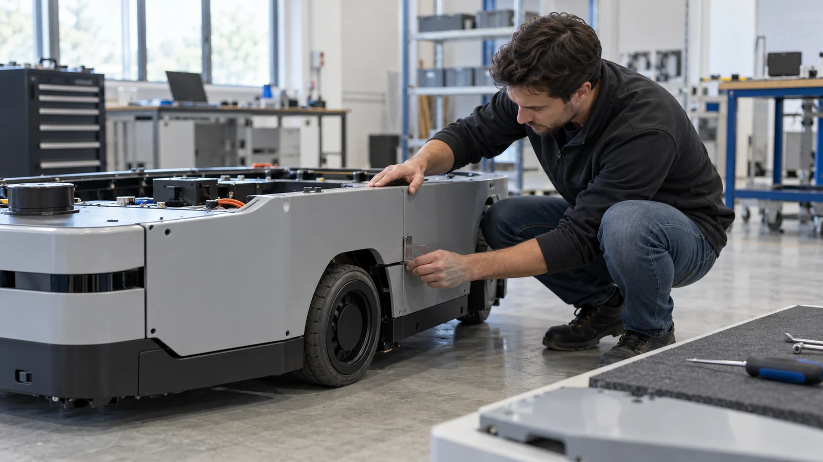
For production validation, sample more than one cavity and more than one molding run when applicable. Include the environmental and handling conditions that matter to the application. If the panel is exposed to repeated impact, temperature change, or cleaning chemicals, test the assembled interface after conditioning rather than relying only on a room-temperature visual review.
| What to verify | Why it matters | Useful evidence |
|---|---|---|
| Flatness and fit | Prevents rocking, gaps, and forced assembly | Datum-based measurements on the vehicle |
| Clip and boss durability | Service access can load features repeatedly | Removal/reinstallation and torque checks |
| Sensor interface | Panel movement can affect alignment or field of view | Position check before and after vibration or service |
| Surface appearance | Large show areas reveal flow and cooling variation | Defined lighting and acceptance criteria |
What to include in an RFQ
Send the 3D model and drawing, target annual and launch quantities, material or performance constraints, cosmetic zones, mounting interfaces, and any assembly or service requirements. Mark the surfaces that control sensor alignment or vehicle clearance. If the part replaces an existing panel, include the current failure mode and photos of the installed condition.
That information lets a tooling and molding review distinguish a cosmetic shell from a load-bearing component, identify likely warpage risks, and propose a validation plan before steel is committed. The useful question is not simply whether a large panel can be molded; it is whether the molded geometry can repeatedly fit the vehicle without creating service, alignment, or appearance problems.
Questions buyers ask
Can a large AGV cover be molded as one piece?
Sometimes. The decision depends on machine and mold capacity, flow length, part stiffness, handling, and how the shell is assembled. Splitting the design may reduce distortion or simplify service, while a one-piece panel may reduce seams and part count. Review both architectures against the actual vehicle.
Should sensor mounts be molded into the outer cover?
Only when the cover provides a stable enough datum for the sensor’s alignment needs. If the panel flexes during fastening, vibration, or service, use a more rigid mounting structure and keep the cosmetic skin separate from the precision location.
Does a filled resin guarantee a stiffer panel?
No. Reinforcement can increase stiffness in a specific grade, but fiber orientation, geometry, weld lines, and molding variation affect the finished part. Validate the molded panel and its assembly rather than relying on a generic material label.