
An AGV drive wheel has to transmit torque, maintain contact with the floor, and survive repeated starts, turns, and stops. AGV drive wheel overmolding can make sense when a rigid hub needs a molded traction layer and the chosen material, geometry, and duty cycle support a durable interface. It is not a universal replacement for a separately manufactured tire or cast elastomer: heat buildup, wear, load, floor conditions, and repair strategy can change the answer.
Choose the wheel architecture before choosing the polymer
First decide whether the wheel is a single molded component, a rigid hub with a bonded or mechanically retained tread, or a replaceable tire assembled onto a hub. These designs have different tooling, service, and failure consequences. An integrated overmold may reduce assembly steps, but a damaged tread can make the whole wheel harder to repair. A replaceable tire adds an interface and assembly operation but can simplify maintenance.
The drive requirement also matters. A powered wheel sees torque and localized contact; a caster or guide wheel may have a different load path and wear pattern. Record wheel diameter, expected load range, speed, acceleration, duty cycle, floor material, debris, cleaning agents, and whether the vehicle turns by differential drive. Without those conditions, statements such as “high grip” or “long life” are not testable requirements.
For projects considering a molded two-material component, the site’s overmolding process overview is the relevant process reference. The robotics application page provides broader context on injection-molded components for robotics.
The hub interface decides whether the overmold stays put
A wheel can fail at the interface even when the tread material itself is not torn. The overmold may rotate on the hub, peel at an edge, or separate after repeated torque reversals. Chemical adhesion depends on the exact substrate and elastomer grades, surface condition, and process window; a broad material-family pairing is not enough to guarantee a bond.
Designers can also use mechanical retention: through-holes, undercuts, grooves, ribs, or features that let the molded layer resist rotation and axial movement. These features must be compatible with mold filling, venting, ejection, and the remaining hub strength. A sharp edge at the overmold boundary may become a peel initiation point, while an abrupt change in section can create a local stress concentration.
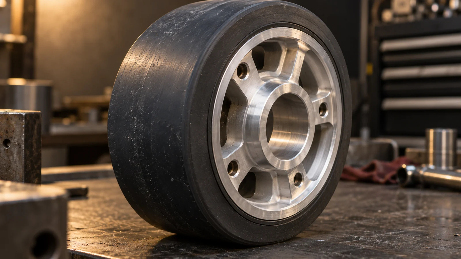
- Specify the exact hub substrate and candidate elastomer grades.
- Separate chemical-bond expectations from mechanical-retention requirements.
- Place retention features where they can be filled and inspected.
- Define how the interface will be tested after thermal and mechanical conditioning.
Material candidates such as TPE or TPU should be compared by grade, not just acronym. The site’s thermoplastic elastomer material information can support an initial discussion, but the final pairing still needs supplier compatibility evidence and molded-part validation.
Traction is a system property—not a tread-texture promise
Grip depends on the wheel material, surface texture, normal load, floor finish, contamination, temperature, and how the vehicle accelerates and turns. A tread pattern that works on a clean test plate may behave differently on a dusty warehouse floor or over a joint between floor sections. Softer material is not automatically better: it may increase contact, but could also deform, heat, or wear faster under the actual duty cycle.
Translate “good traction” into measurable acceptance criteria. For example, define the maximum permitted wheel slip under specified load and acceleration, braking distance on the intended floor, or the change in behavior after a defined wear interval. The exact test should reflect the vehicle design and safety analysis; avoid copying a generic test value from a different wheel or surface.
Texture and geometry need practical review too. Deep grooves can trap debris, increase local stress, or complicate cleaning. A very smooth tread may provide predictable contact on one surface but lose performance when dust or liquid is present. Match the tread features to the floor and maintenance regime, then test the whole drive assembly.
Check heat, wear, and cleaning exposure as one duty cycle
Repeated slip and deformation generate heat. Turning in place, carrying a heavy load, running on a high-friction surface, or accelerating frequently can make the tread work harder than a straight-line demonstration suggests. Heat can change stiffness and wear behavior, and it can also affect the hub interface. A short bench test may not reveal this because the wheel has not reached a representative thermal state.
Track tread wear across the wheel width and circumference. Uneven wear can point to alignment, load distribution, runout, chassis geometry, or vehicle control issues—not only a material problem. If the vehicle operates near oils, floor cleaners, or process chemicals, include those exposures in conditioning tests. Compatibility should be verified for the exact grade and contact conditions.
- Run the wheel under representative load and motion, including turning and starts/stops.
- Record temperature, slip, wear location, and visible interface changes.
- Repeat after realistic cleaning or contaminant exposure where relevant.
- Inspect both the tread and hub for rotation, edge lift, cracks, or debris damage.
Validate runout and durability together
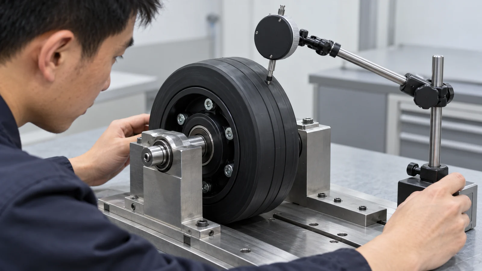
Concentricity and radial runout influence vibration, contact pressure, and how evenly the tread wears. A wheel that passes a material bond test can still cause vehicle oscillation if the molded layer is eccentric or if the hub is not located consistently during molding. Define the datum scheme on the hub and the finished wheel, then measure the assembled part.
Validation should connect manufacturing checks to vehicle behavior. Inspect dimensions and runout, test torque transfer across the interface, and run loaded motion cycles on a representative floor. If the tire is replaceable, also verify retention and serviceability after removal and reassembly. Acceptance criteria should be agreed before trial parts are evaluated.
Overmolded traction layer or separate tire?
| Decision factor | Overmolded tread | Separate tire or bonded assembly |
|---|---|---|
| Part count | Can combine hub and tread in one molded assembly | Requires a separate component and assembly step |
| Repair strategy | May require replacing the complete wheel | May allow tire-only replacement, depending on design |
| Interface risk | Bond and mechanical retention must survive molding and use | Assembly interface still needs retention and durability checks |
| Tooling and volume | Dedicated tooling is justified only when design and demand support it | May use different supplier or tooling routes |
| Best next step | Prototype the material/hub pair and validate the vehicle cycle | Compare assembly consistency, replacement access, and lifecycle needs |
Neither column is automatically lower cost over the wheel’s service life. Compare the complete route: tooling, assembly, inspection, replacement labor, downtime, and failure consequences. Include wheel count per vehicle and expected maintenance access in the decision.
Questions buyers ask
Can an injection-molded overmold replace cast polyurethane?
That cannot be decided by material family names alone. Compare exact grades, wheel loads, speed, heat buildup, wear, floor conditions, and service life. A molded thermoplastic elastomer concept may suit some architectures; other applications may need a different material or construction.
How can tread separation be prevented?
Use a compatible material pair where chemical bonding is required, add mechanical retention where appropriate, avoid peel-sensitive edge geometry, and test the molded interface after representative conditioning and torque cycles.
What should be sent for an initial review?
Provide the hub and wheel CAD, target material or operating constraints, load and motion profile, floor type, cleaning exposure, production quantity, and any current wear or slip data. These details help define a meaningful prototype and validation plan.