
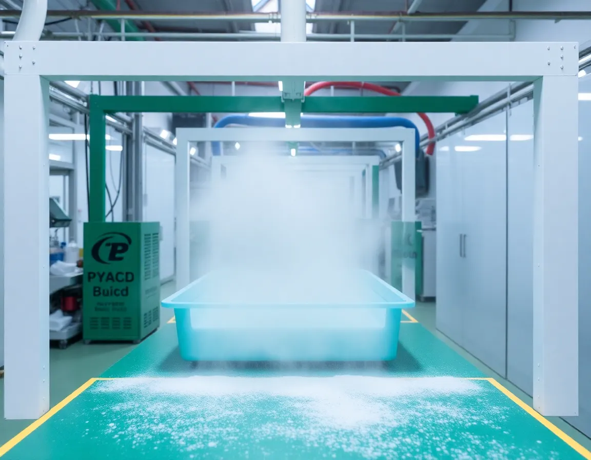
Einleitung: Die Welt der Reinraum-Kunststoffmontage mit hohem Einsatz
In Branchen von der Halbleiterfertigung bis zur pharmazeutischen Verpackung ist die Montage von Kunststoffkomponenten in einer kontrollierten Umgebung nicht nur ein Verfahrensschritt – sie ist ein kritischer Faktor für Produktausbeute, Sicherheit und behördliche Konformität. Die Reinraum-Kunststoffmontage bezieht sich auf das Verbinden, Befestigen, Schweißen oder Kleben von Polymerteilen in einer Einrichtung, in der die Konzentration luftgetragener Partikel, Temperatur, Luftfeuchtigkeit und Druck sorgfältig reguliert werden. Im Gegensatz zur Standardfertigung erfordert dieser Prozess eine einzigartige Kombination aus Materialwissenschaft, Kontaminationskontrolle und Präzisionstechnik. Ein einziges mikroskopisches Partikel, eine elektrostatische Entladung oder eine unsachgemäße Handhabungstechnik kann eine gesamte Charge medizinischer Geräte oder Mikroelektronik unbrauchbar machen.
Trotz seiner Bedeutung unterschätzen viele Ingenieure und Produktionsleiter die Komplexität. Sie nehmen an, dass ein Reinraumanzug und ein HEPA-Filter ausreichen. Die Realität ist viel nuancierter. Als professioneller Content-Autor mit tiefem Brancheneinblick habe ich beobachtet, dass die meisten Montagefehler nicht am Kunststoff selbst liegen, sondern an vermeidbaren Verfahrens- und Umgebungsversehen. Dieser Artikel analysiert die sieben kritischsten Fehler bei der Reinraum-Kunststoffmontage und bietet umsetzbare Strategien zur Risikominderung, Abfallreduzierung und Sicherstellung der Konformität mit strengen Standards wie ISO 14644 und GMP-Richtlinien. Ob Sie Luer-Connectors für Spritzen oder interne Gehäuse für Luft- und Raumfahrtelektronik montieren, die Vermeidung dieser Fallstricke schützt Ihren Ruf und Ihr Endergebnis.
Fehler #1: Ignorieren materialspezifischer Ausgasung und flüchtiger organischer Verbindungen (VOCs)
Der erste und vielleicht heimtückischste Fehler ist, alle Kunststoffe als inert zu behandeln. In einem Reinraum wird die Luftqualität nicht nur durch Partikel, sondern auch durch chemische Kontamination definiert. Viele technische Kunststoffe – wie Polycarbonat, ABS und bestimmte Polyamide – geben flüchtige organische Verbindungen (VOCs) ab und unterliegen einer Ausgasung, insbesondere wenn sie während des Ultraschallschweißens oder Lösungsmittelklebens Wärme ausgesetzt sind. Diese chemischen Emissionen können auf empfindlichen optischen Oberflächen kondensieren, Mikroschaltungen korrodieren oder sterile pharmazeutische Fläschchen kontaminieren.
Die verborgene Gefahr von Additiven
Kunststoffformulierungen enthalten oft Weichmacher, Flammschutzmittel und Trennmittel. Während der Montage können Reibung oder erhöhte Temperaturen dazu führen, dass diese Additive an die Oberfläche migrieren. Wenn Ihr Reinraumprozess dies nicht berücksichtigt, riskieren Sie eine Kreuzkontamination benachbarter Komponenten. Der kritische Fehler besteht darin, keinen Materialqualifikationstest unter simulierten Montagebedingungen durchzuführen. Sie müssen den Gesamtmassenverlust (TML) und das gesammelte flüchtige kondensierbare Material (CVCM) gemäß ASTM E595 messen. Für Anwendungen mit hoher Zuverlässigkeit spezifizieren Sie niedrig ausgasende Qualitäten wie PEEK oder PTFE und stellen Sie sicher, dass Ihre Montageumgebung über eine angemessene chemische Filtration (Aktivkohle) zusätzlich zu Partikelfiltern verfügt.
Gehen Sie außerdem nicht davon aus, dass ein "sauberes" Kunststoffgranulat nach der Extrusion sauber ist. Der Montageprozess selbst – insbesondere Lasermarkierung oder Heißplattenschweißen – kann Abbauprodukte erzeugen. Eine bewährte Praxis ist die Implementierung eines Vormontage-Ausheiz- oder Vakuumentgasungszyklus für Komponenten, die geschweißt oder geklebt werden, um oberflächengebundene Feuchtigkeit und nicht umgesetzte Monomere zu entfernen, bevor sie in die kritische Montagezone gelangen.
Fehler #2: Übersehen der Kontrolle elektrostatischer Entladungen (ESD) bei nicht leitfähigen Polymeren
Kunststoffe sind natürliche Isolatoren. Wenn zwei Polymeroberflächen während der Montage aneinander reiben – zum Beispiel beim Einrasten oder bei der Vibrationswendelförderung – erzeugen sie erhebliche statische Ladungen, die oft 10.000 Volt überschreiten. Dies ist ein katastrophales Versehen in Reinräumen, in denen elektronische Komponenten vorhanden sind. Der Fehler ist zweifach: die Annahme, dass ein Ionisator optional ist, und die Verwendung von Standard-Kunststoffwerkzeugen, die nicht statisch ableitend sind.
Warum statische Aufladung ein stiller Killer ist
Statische Entladung zerstört nicht nur empfindliche Halbleiterchips, sondern zieht auch luftgetragene Partikel wie ein Magnet an. Ein geladenes Kunststoffteil zieht sub-Mikrometer-Partikel aus der Luft an und macht den Zweck des Reinraums zunichte. Viele Bediener glauben, dass der Kunststoff geerdet ist, weil sie ESD-sichere Handgelenkbänder tragen. Das ist falsch. Nicht leitfähige Kunststoffe können nicht geerdet werden; sie erfordern eine aktive Neutralisierung. Der kritische Fehler besteht darin, keine Ionisierungsgebläse und antistatische Lametta an jeder Montagestation einzusetzen, an der Kunststoffteile gehandhabt, bewegt oder gestapelt werden.
Darüber hinaus ist die Wahl der Montagevorrichtungen von Bedeutung. Aluminiumspannvorrichtungen sind ausgezeichnete Leiter, können aber Teile beschädigen; Standard-Nylon- oder Acetalvorrichtungen erzeugen Ladung. Verwenden Sie stattdessen Vorrichtungen, die aus statisch ableitendem Acetal (ESD-Acetal) gefertigt oder mit einem leitfähigen PTFE beschichtet sind. Überwachen Sie außerdem die Luftfeuchtigkeit – wenn Ihr Reinraum zu trocken ist (unter 40 % relativer Luftfeuchtigkeit), steigt die statische Aufladung exponentiell an. Halten Sie einen strengen Bereich der relativen Luftfeuchtigkeit von 45–55 % ein, um Ladungen auf natürliche Weise abzuleiten. Die Umsetzung dieser Kontrollen reduziert die Partikelanziehung und verhindert latente Ausfälle in elektronischen Baugruppen.
Fehler #3: Unzureichende Kontrolle von Reibung und Partikelerzeugung bei Press- und Schnappverbindungen
Die mechanische Montage von Kunststoffen, wie das Aufpressen einer Nabe auf eine Welle oder das Einrasten einer Abdeckung auf ein Gehäuse, erzeugt grundsätzlich Abriebpartikel. Dies ist ein grundlegendes physikalisches Problem: Wenn zwei Oberflächen unter Druck aneinander gleiten, scheren mikroskopische Unebenheiten ab und erzeugen Partikel. In einem Reinraum sind diese Partikel der Feind. Der kritische Fehler besteht darin, Montageprozesse zu entwerfen oder auszuwählen, die auf hochreibungsbedingten Presssitzen basieren, ohne das Partikelbudget zu berücksichtigen.
Die Reibung wegentwickeln
Um dies zu vermeiden, müssen Sie die Verbindungskonstruktion überdenken. Verwenden Sie anstelle einer engen Metall-auf-Kunststoff-Presspassung eine konische Einführschräge mit einer gleitfähigen Beschichtung (z. B. eine dünne Schicht eines silikonfreien Trockenschmierstoffs wie Molybdändisulfid oder ein medizinisches PFPE). Alternativ wechseln Sie zu Laserschweißen oder Orbitalnieten bei dem das Material lokal erhitzt und ohne Gleitkontakt geformt wird. Wenn Schnappverbindungen unvermeidbar sind, stellen Sie sicher, dass der Schnapparm mit einem kontrollierten Ablenkwinkel (weniger als 30 Grad) ausgelegt ist, um das Abrasieren zu reduzieren.
Ein weiterer übersehener Aspekt ist die tooling material. Hardened steel punches can micro-machine the plastic surface, creating flakes. Use tools with a mirror-polished finish or, better yet, use urethane or rubber-coated anvils that conform to the part without cutting. Furthermore, implement a vibration analysis on your automated assembly press; excessive vibration causes chatter, which dramatically increases wear. Finally, after any mechanical joining step, include an air knife or vacuum extraction point immediately downstream to capture debris before it migrates. Do not rely on the final wash to remove particles—by then, they have already embedded into other surfaces.
Mistake #4: Using the Wrong Cleaning Agents and Solvents for Post-Assembly Degreasing
After plastic assembly, parts often require cleaning to remove fingerprints, mold release, or machining oils. However, the choice of cleaning solvent is a minefield. Many standard solvents—acetone, isopropyl alcohol (IPA), or chlorinated hydrocarbons—can cause environmental stress cracking (ESC) in amorphous plastics like polycarbonate or polysulfone. The mistake is using a "universal" cleaning process without verifying chemical compatibility with the specific polymer blend and its additives.
The ESC Trap and Residue Issues
Even a brief wipe with IPA can initiate microscopic cracks that propagate under load, leading to premature failure in the field. Instead, use aliphatic hydrocarbon solvents (e.g., heptane) or specialized non-ionic aqueous cleaners with a neutral pH. For critical medical devices, consider CO₂ snow cleaning oder plasma cleaning—these are dry processes that leave zero residue and do not attack the polymer matrix.
Furthermore, the cleaning process itself must be validated. If you use ultrasonic cleaning, the cavitation energy can erode soft plastics like polyethylene. If you use manual wiping, ensure the wipes are low-linting cleanroom wipes (e.g., knitted polyester) and are saturated with the solvent—a dry wipe creates friction and re-deposits oils. Always perform a final rinse with ultra-pure water (18 MΩ-cm) followed by a forced HEPA-filtered air dry. Document the cleaning parameters and perform periodic residue testing via FTIR or ion chromatography to ensure your process remains in control.
Mistake #5: Neglecting Thermal Expansion Mismatch in Welded or Bonded Assemblies
Cleanroom plastic assembly often involves joining dissimilar materials—for example, bonding a polypropylene filter housing to a stainless steel port, or welding a PETG window into an ABS frame. The critical mistake is ignoring the coefficient of thermal expansion (CTE) differences. When the assembly experiences temperature fluctuations during autoclaving, curing, or even normal operation, the differential expansion creates internal stress that can cause bond-line failure, warpage, or micro-cracking.
Designing for Thermal Reality
To mitigate this, you must design the joint to accommodate movement. For adhesive bonding, use a flexible, high-elongation adhesive (e.g., a silicone-based adhesive or a polyurethane with 200% elongation) rather than a rigid cyanoacrylate. For ultrasonic welding, ensure the weld joint is designed as a shear joint rather than a butt joint, allowing slight relative movement without breaking the molecular bond.
Additionally, during the assembly process, control the ambient temperature strictly. If you are welding a part at 22°C but the part was stored at 30°C in a warehouse, the thermal gradient will cause uneven shrinkage. Implement a soak-out period—store all components and fixtures in the cleanroom for at least 24 hours before assembly to equilibrate. For high-precision assemblies, use a climate-controlled assembly chamber with ±0.5°C stability. Finally, perform a thermal cycle test (e.g., -40°C to +85°C for 100 cycles) on your first articles to validate that your joint design and material selection can survive real-world conditions. Skipping this validation is a recipe for field failures.
Mistake #6: Inconsistent Torque and Fastening Protocols for Threaded Plastic Components
Many cleanroom assemblies use threaded fasteners—either self-tapping screws into plastic bosses or threaded inserts. The critical mistake is using the same torque settings as for metal assemblies. Plastics are viscoelastic; they relax under constant load. A screw that is torqued to 10 in-lbs today may lose 30% of its clamping force within 24 hours due to creep and stress relaxation. This leads to loose joints, leaks, and particulate generation from fretting.
The Correct Fastening Strategy
First, never use standard sharp-thread screws. Use screws specifically designed for plastics, such as PT® (Plastic Thread) screws with a 30° thread angle and a blunt tip. These displace material rather than cut it, providing higher pull-out resistance and lower radial stress. Second, use a torque-controlled driver with a slow approach speed. High-speed driving creates heat, which melts the plastic boss and weakens the threads. Set the driver to a low RPM (under 300 RPM) and use a depth-stop or pressure-sensitive shut-off to prevent stripping.
Third, consider the use of metal threaded inserts (heat-staked or ultrasonic-inserted) instead of screws directly into plastic. This provides a robust, reusable thread and eliminates the risk of boss cracking. If you must use self-tapping screws, design the boss with an undersized pilot hole (typically 80-85% of the screw's minor diameter) and a stress-relief counterbore at the top. Finally, implement a torque audit protocol: every hour, assemble a test part and measure the prevailing torque and clamp load. Use a digital torque analyzer that records peak torque and angle. This data will reveal if your fasteners or plastic batches are drifting out of spec. Do not trust the "click" of a manual wrench.
Mistake #7: Failing to Validate the Cleaning and Packaging Interface
The final critical mistake occurs after the assembly is complete: the interface between the cleanroom assembly line and the packaging process. Many manufacturers spend millions on cleanroom assembly only to compromise the product with contaminated packaging materials or by breaking the cleanroom barrier during transfer. The mistake is treating packaging as a secondary concern rather than an integral part of the cleanroom protocol.
The Contamination Handoff
If your assembled plastic part is placed into a standard cardboard box or a non-cleanroom polyethylene bag, it will immediately attract fibers and particles. The packaging must be certified cleanroom-grade (e.g., Class 100/ISO 5 cleanroom bags) and must be compatible with the plastic (no plasticizers that can leach into your part). Furthermore, the transfer from the assembly cleanroom to the packaging cleanroom must be through a pass-through chamber with interlocked doors, not an open doorway. You must also validate the shelf life of the packaged assembly—some plastics continue to outgas and can fog the interior of a sealed pouch.
Additionally, do not overlook the labeling and adhesive used on the packaging. The adhesive on a label can outgas volatile silicones that contaminate the part. Use solvent-free, cleanroom-compatible labels. Finally, establish a particle count verification step just before sealing. Use a liquid particle counter (if the part is rinsed) or a surface particle counter (via swabbing) to ensure the final product meets the required cleanliness level (e.g., ISO 14644-9 for surface cleanliness). If the part fails, you must have a re-cleaning and re-validation loop. This final step is not just about quality—it is about regulatory compliance and patient safety in medical applications.
Conclusion: Building a Culture of Precision
Avoiding these seven critical mistakes in cleanroom plastic assembly is not a one-time checklist; it is a continuous engineering discipline. The common thread among all these failures is a lack of systematic validation—of materials, processes, environmental controls, and packaging. In the world of cleanroom manufacturing, "good enough" is rarely good enough. The cost of a single failed batch due to outgassing, ESD damage, or torque relaxation can exceed the savings of a thousand minor optimizations.
To truly excel, you must adopt a holistic contamination control strategy that integrates material selection, process design, tooling, environmental monitoring, and operator training. Your cleanroom operators must understand why they cannot use a standard rag, why they must slow down the screwdriver, and why the packaging bag is as important as the assembly cell. When you foster this level of awareness, you transform cleanroom assembly from a mere manufacturing step into a competitive advantage—delivering products that are reliable, compliant, and trusted by the most demanding customers in the world.
As you review your current cleanroom plastic assembly operations, ask yourself: Are we measuring outgassing? Are we neutralizing static? Are we validating thermal cycles? Are we auditing torque? If you answered "no" to any of these, you have identified your next improvement project. The path to zero defects is paved with meticulous attention to these seemingly small details. Do not let a microscopic particle or a creeping torque value be the reason your product fails in the field. Take action today.