
A sink mark that remains after increasing packing pressure is a useful clue: the defect may not be controlled by pressure alone. A localized depression on a molded surface can reflect a thick section shrinking as it cools, a gate that freezes before the material can compensate, or a geometry and cooling combination that holds the core too long. Increasing pack blindly may create flash, stress or dimensional drift without changing the underlying cause.
For sink marks injection molding problems, start by locating the depression relative to ribs, bosses, thick transitions and the gate. Then determine whether the visible mark is a surface sink, a subsurface void, or a different surface condition. Those distinctions lead to different corrective actions.
Fast read: if the mark repeats behind a thick feature, inspect wall transitions and local cooling; if it changes with packing time or gate location, verify the gate remains open long enough for compensation; if it appears inconsistently, compare material, process and mold temperature records.
In this article
- Identify what the surface is telling you
- Trace the mark to the part geometry
- Test packing and cooling without guessing
- Redesign the section when process changes stop helping
- Verify the fix against function and appearance
- Frequently asked questions
Identify what the surface is telling you
A sink is a shallow surface depression; an internal void is a cavity within the part that may not be visible from the outside. The two can share a cause—localized shrinkage—but inspection and acceptance differ. Use a consistent light angle, compare parts from the same cavity and, where the application warrants it, inspect a sectioned sample or use an approved nondestructive method. Avoid labeling every dull or wavy patch as a sink before confirming the shape.
Record the mark’s position, size, depth if measurable, cavity and distance from the gate. A repeated depression centered over a boss or rib is stronger evidence of a local mass imbalance than a broad mark that follows a flow path. The distinction also matters to buyers: a cosmetic depression on a hidden surface may have a different acceptance limit from one that affects a sealing face or visible panel.
Trace the mark to the part geometry
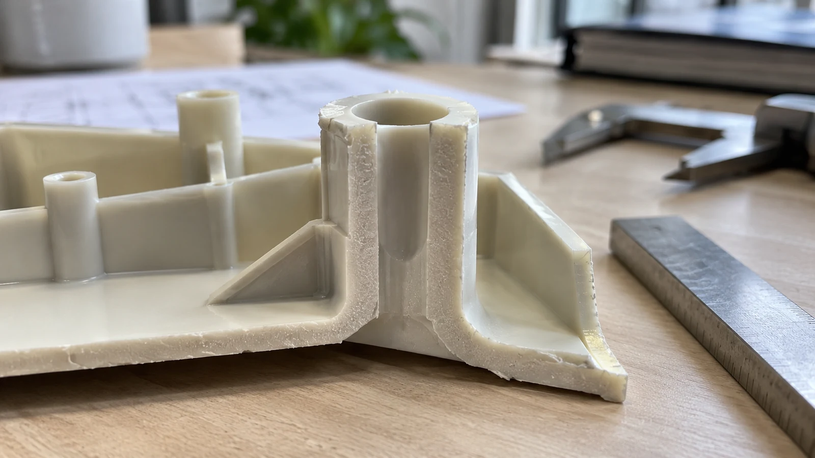
Thick material cools differently from adjacent thin walls. A boss connected to a nominal wall by a heavy junction can retain a hot core; as that material contracts, the outer surface may be pulled inward. Ribs can produce the same effect when they are too thick relative to the wall or meet it with a bulky intersection. The result depends on resin, geometry, mold temperature, cooling layout and process—not a universal rib ratio alone.
| Pattern on the part | Useful next check | Design question |
|---|---|---|
| Depression over a boss or rib root | Local wall mass, cooling and sectioned sample | Can the junction be cored or thinned? |
| Mark near the end of fill | Gate path, pressure transfer and flow balance | Would another gate or flow path help? |
| Variable mark across cavities | Cavity balance, cooling and process records | Are cavities seeing equivalent conditions? |
Use mold flow analysis as a way to examine filling, packing and cooling hypotheses—not as proof that a production part will meet a cosmetic specification. Model assumptions, material data and actual tool conditions still need to be checked.
Test packing and cooling without guessing
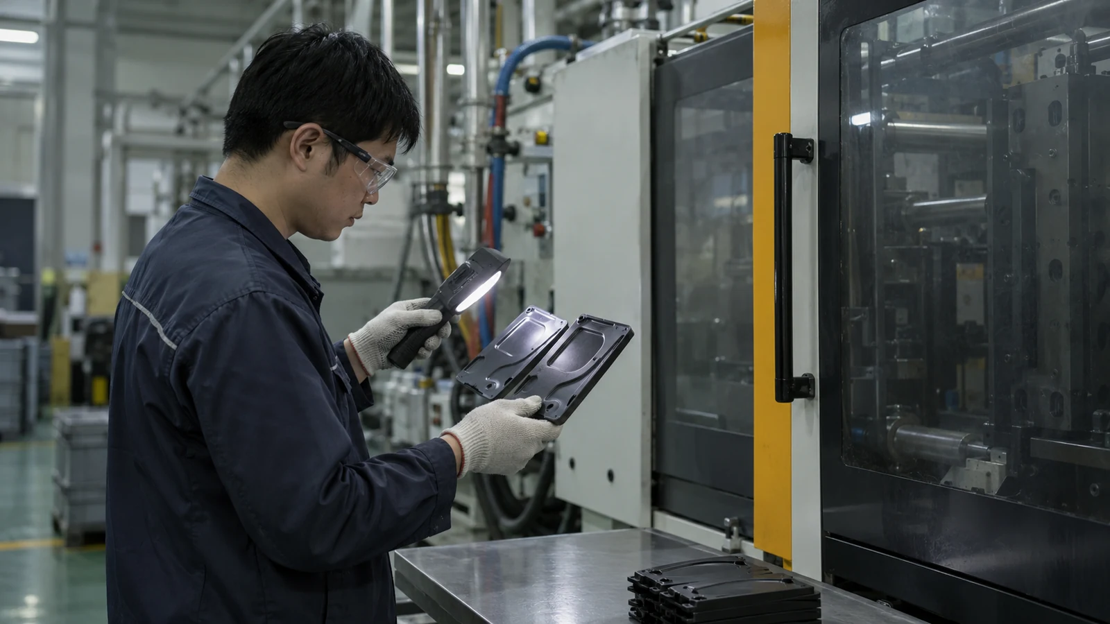
First confirm that the process is stable: resin identity and conditioning, melt and mold temperatures, shot size, transfer point and cycle timing should be documented. Then test packing pressure and duration within the approved process window. If extending pack time changes the sink only until a certain point, that may indicate when the gate stops transmitting pressure; extra time after gate freeze will not provide the same compensation.
Cooling changes can also help, but extending the whole cycle is not automatically the best correction. Compare local mold temperature, cooling-channel condition and ejection behavior. A part that is ejected too warm may distort or show a different surface response; uneven cooling can leave one area shrinking against another. Review the full plastic injection molding process so a cosmetic improvement is not purchased at the cost of cycle stability or dimensional control.
- Hold material and setup constant while establishing a baseline.
- Change one packing variable or cooling variable at a time.
- Record part weight, sink location and critical dimensions by cavity.
- Stop when the response plateaus or another defect appears; revisit geometry and gate design.
Redesign the section when process changes stop helping
If the sink persists after a controlled process study, consider reducing local mass rather than forcing the process harder. Options may include coring a boss, reducing rib thickness, smoothing a thick intersection, redistributing material or changing the gate path. Each option must preserve screw engagement, stiffness, sealing, assembly and the required surface.
These changes belong in a coordinated mold and part design review. A feature that is structurally critical may need a different solution from a cosmetic rib. Where a surface is visible, add an explicit visual acceptance area and lighting method to the drawing or inspection plan; “no sink” without a viewing condition can produce inconsistent decisions.
Verify the fix against function and appearance
Do not approve a correction from one attractive sample. Confirm repeatability across cavities and after the mold reaches its normal operating condition. Compare the revised part against the same viewing angle, measurement method and drawing revision. Recheck fit, assembly, critical dimensions and any mechanical test affected by the changed section.
For a supplier review, send the CAD revision, resin grade, gate and cavity details, photographs with scale, process history and the allowable cosmetic zone. State whether the concern is visible appearance, internal integrity, sealing or assembly. This turns the discussion from “Can you remove the sink?” into a testable engineering decision.
Frequently asked questions
Does increasing packing pressure always remove sink marks?
No. It helps only while pressure can reach the region and the part and tool can tolerate the change. If the gate has frozen or the local section is too massive, more pressure may add flash or stress without removing the depression.
Are sink marks and voids the same defect?
No. A sink is visible as a surface depression; a void is an internal cavity. They can share shrinkage-related causes, but confirming the defect type may require sectioning or another suitable inspection method.
Can a sink mark be accepted?
Acceptance depends on location, visibility, function and the agreed specification. Define the viewing conditions and limits, especially for sealing, mating or appearance-critical surfaces.