
Cooling is often the longest part of a molding cycle, which makes it an obvious target when a program needs more output. Yet a part that can be pushed out sooner is not necessarily a part that is stable, flat, or ready for assembly. A useful cooling-time decision balances heat removal with the part’s stiffness at ejection, dimensional requirements, and the mold’s ability to remove heat evenly.
Short answer: Cooling time depends chiefly on the part’s thick sections, resin thermal behavior, mold temperature, and how effectively the tool transfers heat to coolant. Lowering a timer alone does not improve a process. Confirm the ejection condition, dimensions, appearance, and repeatability on the actual material and mold.
In this article:
- What “cooling time” means in a cycle
- Why some parts cool more slowly
- What a calculation can—and cannot—tell you
- Where to look before reducing the timer
- How to validate a shorter cooling phase
- Frequently asked questions
What “cooling time” means in a cycle
In a molding sequence, cooling usually refers to the time needed for the polymer to lose enough heat to be ejected without unacceptable distortion, sticking, or surface damage. The machine’s programmed cooling timer is not always the same as total cooling experienced by the part: screw recovery and other operations can overlap, and the part continues to cool after it leaves the mold.
Keep cooling time separate from total cycle time. The overall cycle may also include filling, packing and holding, mold movement, ejection, and part handling. A change that shortens the cooling timer may not shorten the machine cycle if another step still controls the sequence.
Why some parts cool more slowly
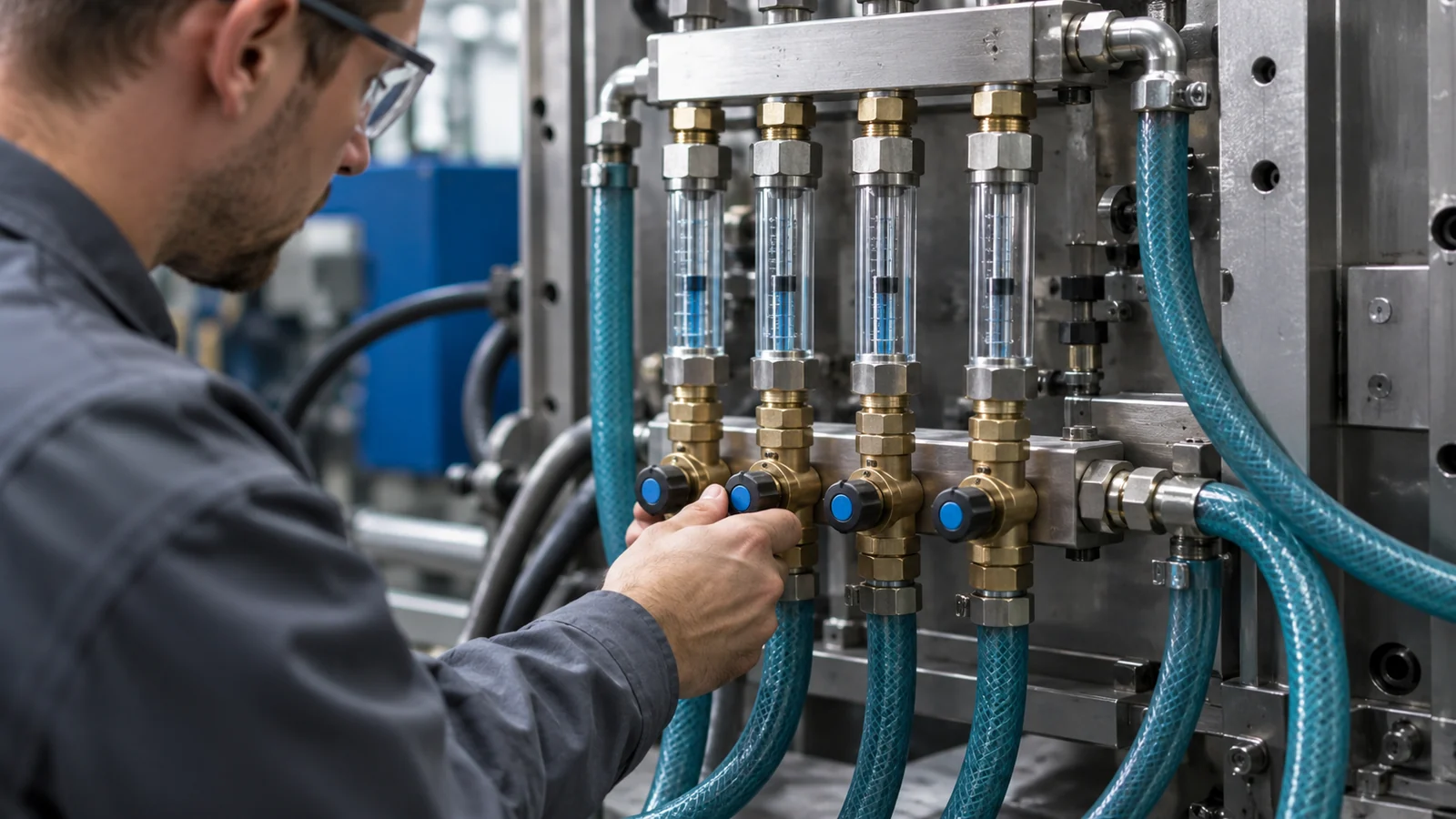
Heat leaves the polymer through the mold steel and into the cooling circuit. The distance from a thick section to an effective cooling surface matters, so a heavy boss or abrupt wall transition may remain hot after adjacent thin walls are ready. Uneven thermal conditions can create differential shrinkage, sink, or warpage even when the average part temperature appears acceptable.
Material properties also affect heat transfer and the temperature at which a part can be safely ejected. Different grades within one resin family may have distinct processing windows, and semi-crystalline materials behave differently from amorphous materials as they solidify. Use grade-specific supplier guidance rather than assigning one time to a broad material name.
The mold circuit can be the bottleneck. Inlet and outlet temperatures, coolant flow, channel placement, deposits, and circuit balance influence how well the tool carries heat away. A cold inlet alone does not prove that the cavity is being cooled uniformly. BASF’s technical information on estimating cooling time explains that estimates depend on material and thermal conditions; treat such calculations as planning tools, not guaranteed production settings.
What a calculation can—and cannot—tell you
Analytical estimates can help compare a thin wall with a thicker one or evaluate whether a proposed geometry change is likely to matter. Many simplified methods assume idealized heat transfer and a representative wall thickness. Real components have ribs, bosses, varying wall sections, different distances to channels, and local constraints that a single average cannot represent.
Therefore, do not present one calculated number as the finished process time. The estimate should be checked against actual mold temperatures, part geometry, resin grade, and ejection behavior. Where geometry is complex, simulation can identify thermal hot spots and compare design options; physical sampling then checks the tool and process. The site’s mold flow analysis page outlines how fill, pack, and warp considerations fit into an engineering review.
Where to look before reducing the timer
Work from the part and tool outward:
- Review thick sections. Check bosses, ribs, intersections, and abrupt transitions. A geometry adjustment can reduce a hot spot more effectively than changing a machine setting.
- Check circuit performance. Confirm that each circuit flows as intended and that inlet/outlet temperatures are stable. Look for an imbalanced or obstructed path.
- Review channel-to-cavity distance. Cooling near a critical thick area can be ineffective if the steel path is too long or the circuit does not follow the heat distribution.
- Consider resin and mold temperature together. The target is consistent quality, not the lowest possible temperature.
- Review ejection support. Part stiffness, draft, ejector layout, and surface condition determine whether the molded shape survives release.
These decisions should be made alongside the tool layout and maintenance needs. A cooling change must preserve adequate steel strength and keep circuits serviceable. The broader custom mold-making review should account for geometry, cooling, venting, and the expected production duty.
How to validate a shorter cooling phase
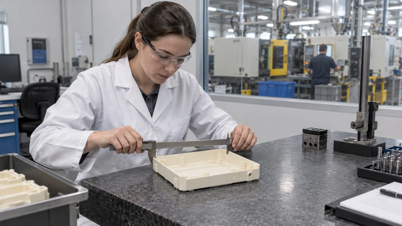
Capture a stable baseline before changing the timer: material and lot, process settings, part weight, mold and coolant temperatures, cavity identity, cycle timing, and critical inspection results. Then reduce the cooling time in controlled increments while keeping other variables stable. Inspect parts immediately after ejection and again after they reach their normal conditioning state; some distortion is delayed.
Do not evaluate one cavity or one shot only. Check each cavity for sticking, drag, ejector witness, warpage, sink, and dimensions. Repeat the test over enough consecutive cycles to reveal drift. If the process becomes unstable, restore the known-good setting and investigate the heat-transfer or ejection limitation rather than forcing a shorter number.
A cooling target is credible only when it is tied to an agreed measurement and part acceptance. During a formal mold trial and validation, record the conditions and the evidence used to accept the setting.
Frequently asked questions
What is a typical cooling time for injection molding?
There is no reliable single value for all parts. Wall thickness, resin, mold temperature, channel design, and ejection requirements change the result. Use the actual tool and material to establish a validated setting.
Does thicker plastic always need more cooling?
Thicker sections generally retain heat longer, but local geometry and cooling effectiveness matter. A thick rib near a well-designed circuit may behave differently from an isolated boss or a thick wall far from the coolant.
Can I shorten cooling by using colder water?
Potentially, but a colder inlet does not guarantee uniform part cooling. Excessive or uneven thermal changes may affect surface replication, stress, or dimensions. Review the full thermal circuit and validate the part.
How do I know if the part is being ejected too hot?
Look for distortion, sticking, scuffing, ejector marks, or dimensions that change after ejection. Measure the part against its drawing and inspect multiple cavities over repeated cycles.
Next step: For a meaningful review, provide the resin grade, 3D model or wall-thickness map, current cycle breakdown, mold-temperature readings, and the dimensions or appearance features that must remain stable.