
Designing multi-material components for single-press dual-shot manufacturing requires strict adherence to rotational clearances, wall thickness proportions, and interfacial sealing geometry. Errors in CAD modeling frequently result in catastrophic mold collisions during 180-degree platen rotation or severe cosmetic flashing over primary substrate boundaries. Meticulous design for manufacturability (DfM) rules eliminate expensive steel modifications and guarantee seamless multi-polymer integration.

Understanding how the primary substrate shrinks before second-shot encapsulation allows product designers to pre-compensate CAD features accurately. This technical engineering manual examines wall thickness rules, rotational clearance requirements, mechanical interlocking geometry, and shut-off land designs.
Wall Thickness Ratios and Draft Angles for 2K Components
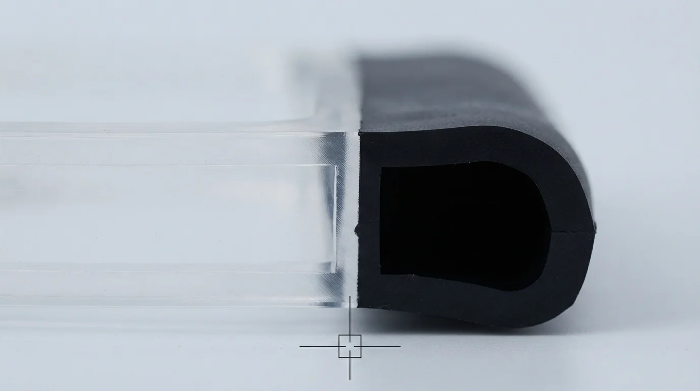
Adhering to a standardized two shot injection molding design guide ensures that both material stages cool uniformly without developing sink marks or internal voids. Controlling wall thickness ratios between the rigid substrate and flexible overmold dictates filling stability. Nominal wall thickness for primary substrates molded from Polycarbonat (PC) oder ABS should remain between 1.5 mm and 3.0 mm.
Secondary elastomeric layers of TPE oder TPU should match or remain slightly thinner than the underlying substrate to prevent thermal sink depressions. Draft angles on vertical substrate walls must be specified at 1.5° to 2.0° minimum to ensure clean part release from the primary cavity before 180-degree rotation. Table 1 below outlines essential CAD design rules for multi-shot components:
| 2K CAD Feature | Recommended Design Rule | Physical Defect if Violated | Tooling Optimization Strategy |
|---|---|---|---|
| Primary Substrate Wall | 1.5 mm – 3.0 mm Uniform | Sink marks & differential warpage | Maintain uniform nominal thickness with gradual tapers |
| Secondary Overmold Wall | 1.0 mm – 2.5 mm Thickness | Short shots (<1.0mm) or sink marks (>3.0mm) | Ensure smooth flow paths without restrictive gates |
| Vertical Draft Angle | 1.5° – 2.0° Minimum Taper | Substrate drag scuffs during core rotation | Increase draft on deep core draw pockets |
| Rotational Cavity Clearance | 0.1 mm – 0.2 mm Step Relief | Crushing first-shot substrate upon clamp-up | Machine relief pockets on secondary cavity steel |
Designing Rotational Clearances & Shut-Off Lands
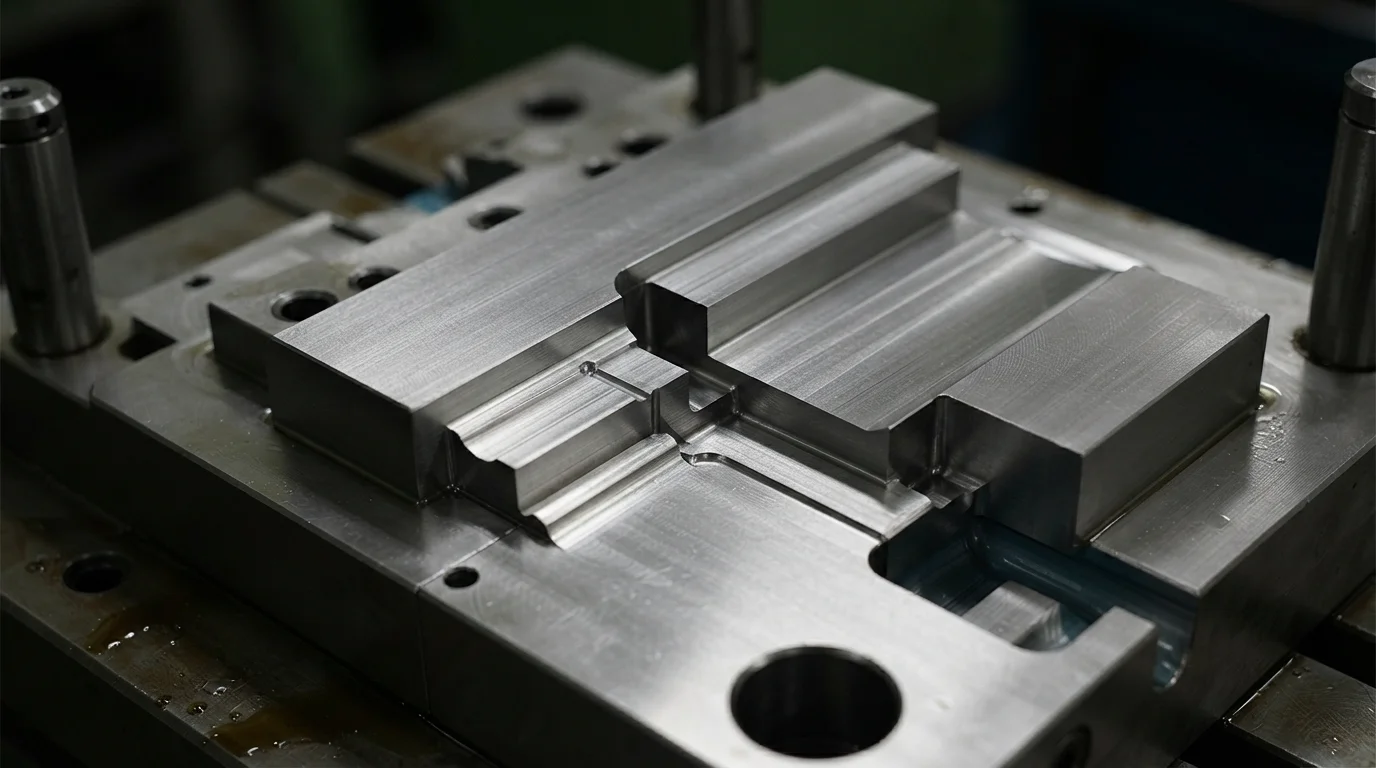
Applying principles from this two shot injection molding design guide prevents tool steel collisions during the 180-degree mold rotation cycle. Designing adequate rotational clearances requires creating relief pockets measuring 0.1 mm to 0.2 mm in the secondary cavity steel. Relief pockets prevent the secondary mold cavity from crushing or scuffing the pre-molded substrate during high-pressure clamp-up.
Precision Schließflächen ground with 90-degree sealing shoulders create positive mechanical barriers against soft elastomer leakage. Maintaining shut-off land fitment tolerances tighter than 0.01 mm ensures crisp visual color separation without cosmetic flash.
Rotational tooling engineering steps include:
- Cavity relief pocket design—Machining 0.15 mm clearance steps on secondary cavity faces prevents substrate scuffing upon mold closure.
- Perimeter shut-off step inclusion—Incorporating a 0.5 mm 90-degree step along the overmold edge creates a sharp cutoff line.
- Substrate shrinkage pre-compensation—Accounting for primary shot thermal contraction ensures exact fitment inside secondary cavities.
- Gate location separation—Positioning secondary hot runner drops away from primary gates prevents substrate remelting.
Mechanical Locking Features: Dovetails, Holes & Undercuts
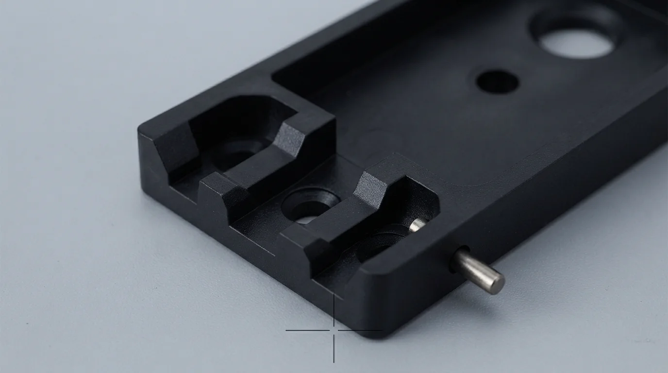
Chemical adhesion between polymers can weaken when components face aggressive cleaning chemicals, moisture, or dynamic cyclic shear. Incorporating mechanical locking features into the rigid plastic substrate provides permanent physical retention that prevents delamination.
Substrates molded from polar engineering plastics like glass-filled PA66 benefit substantially from mechanical locking channels. Designing 90-degree dovetail grooves, undercuts, and through-holes allows molten elastomer to flow through the substrate and rivet on the opposite side. Following an established two shot injection molding design guide eliminates interfacial peeling risks across extended automotive and medical lifecycles.
Why Choose JUCHENG for 2K DfM Review & Tooling
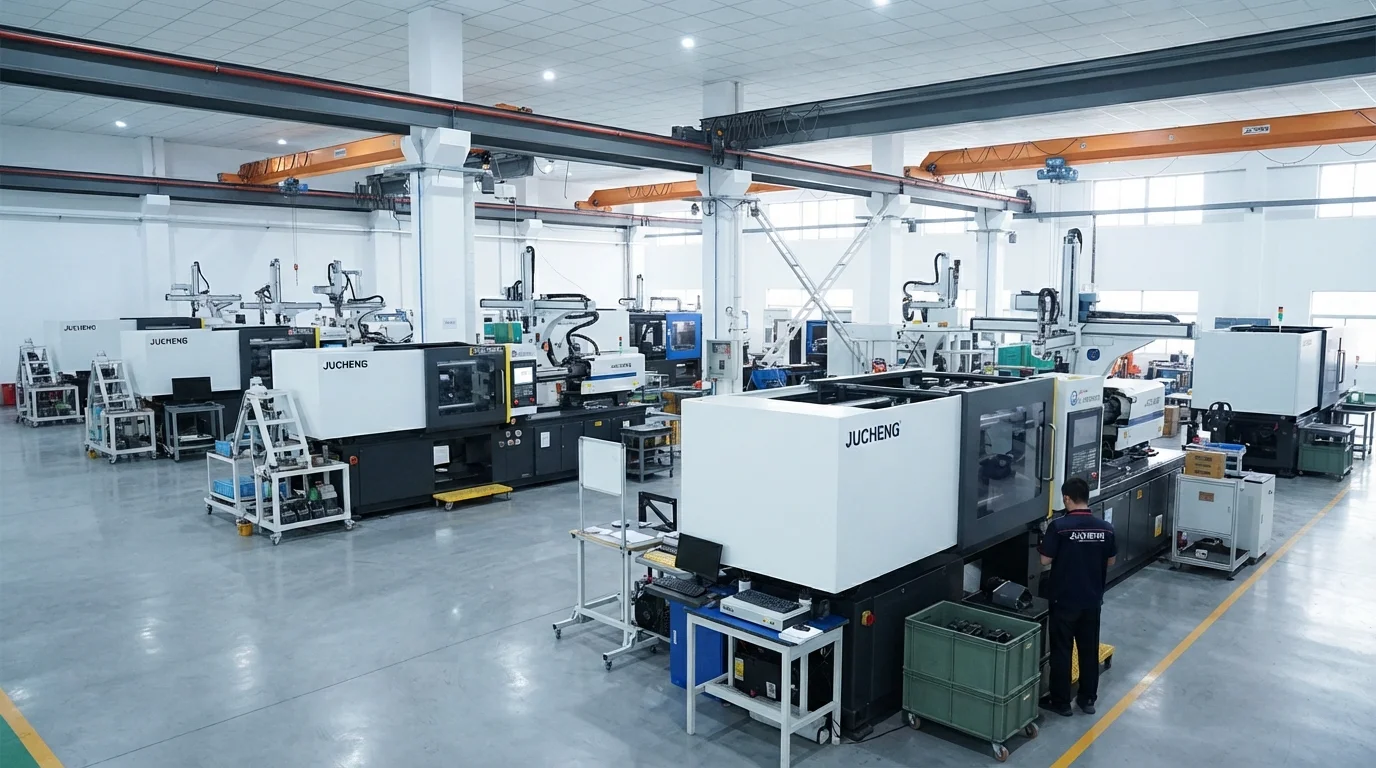
Partnering with JUCHENG provides access to an advanced manufacturing facility housing 35+ automated injection presses ranging from 15T to 3000T clamping force. Operating an in-house tool room with 25 sets of 5-axis CNC machines permits precise machining of shut-off steel lands from hardened S136-Edelstahl oder H13-Werkzeugstahl. Our engineering team delivers a free 24-hour DfM review for every CAD submission, analyzing substrate wall thickness, draft angles, and rotational clearances before cutting steel.
Quality management systems certified to IATF 16949 and ISO 13485 back every multi-shot production run, offering full PPAP Level 3 documentation for automotive programs. Operating an ISO Class 8 cleanroom molding department protects medical components from particulate contamination during molding and drop-packaging. Following a strict two shot injection molding design guide prevents tooling collisions and flash during two shot injection molding.
Häufig gestellte Fragen (FAQs)

Why are rotational cavity clearances critical in 2K mold design?
Rotational cavity clearances provide 0.1 mm to 0.2 mm relief in the secondary mold cavity to prevent crushing or scratching the pre-molded substrate when the mold closes after 180-degree rotation. Inadequate clearance damages the substrate and destroys mold shut-off lands.
What is the recommended wall thickness ratio between first and second shots?
Recommended design rules dictate that the secondary overmold wall thickness should remain equal to or slightly thinner than the primary rigid substrate, typically 1.0 mm to 2.5 mm. Thicker secondary walls cool slower, creating sink marks and thermal shrinkage distortion.
How do shut-off lands prevent second-shot flash in 2K molding?
Tooling shut-off lands clamp firmly against the rigid substrate along a 0.5 mm wide 90-degree sealing step. Maintaining shut-off steel fitment tolerances tighter than 0.01 mm blocks low-viscosity soft elastomer melt from bleeding over cosmetic substrate boundaries.
Can sharp internal corners cause delamination in 2K parts?
Sharp internal corners create localized notch stress concentrations and impede smooth elastomer flow. Adding generous radii (minimum 0.5 mm) at all transition corners promotes uniform melt packing and enhances interfacial bond durability.
How does primary substrate shrinkage affect secondary cavity fitment?
Primary substrates shrink slightly during cooling before 180-degree rotation occurs. Tooling engineers must calculate volumetric shrinkage rates and pre-compensate secondary cavity dimensions to ensure a tight seal without pinching the substrate.
Why is a 24-hour DfM review essential before cutting 2K mold steel?
Conducting an early DfM review evaluates rotational clearances, shut-off angles, and gate placements while CAD files are still digital. Identifying potential flash or collision risks early eliminates expensive mold rework and long tooling delays.