
An injection mold lifter is useful when an internal undercut blocks ejection but can clear through a controlled angled movement. It is not simply a smaller side slide: the lifter travels with the ejector system, so its motion, part contact, and timing must work together. Review the feature within the whole custom mold design before choosing the mechanism.
Start with the trapped surface and draw its release path. If redesign, an open slot, or a parting-line change preserves function, those options may reduce moving steel and maintenance. Use a lifter when the feature justifies its added motion.
In this guide:
When is a lifter a better fit than a slide?
A lifter is considered for an internal undercut that can move diagonally away from the molded feature during ejection. A straight side core is often more direct when the feature needs dedicated lateral withdrawal. Geometry, travel, and mold layout decide; neither mechanism is a universal default.
Undercut depth, draft, wall thickness, ejection direction, and nearby ribs determine whether the lifter can clear without dragging. Deep features may require excessive travel or leave the lifter too slender to remain rigid. Review the part in section as well as in the full mold assembly.
How should lifter movement be coordinated?
The ejector plate drives the lifter forward while its guide path creates lateral displacement. The part must stay supported as the undercut clears. Otherwise, the feature can flex, whiten, crack, or remain caught. Show the full motion and confirm that the lifter clears before handling or robot takeout.
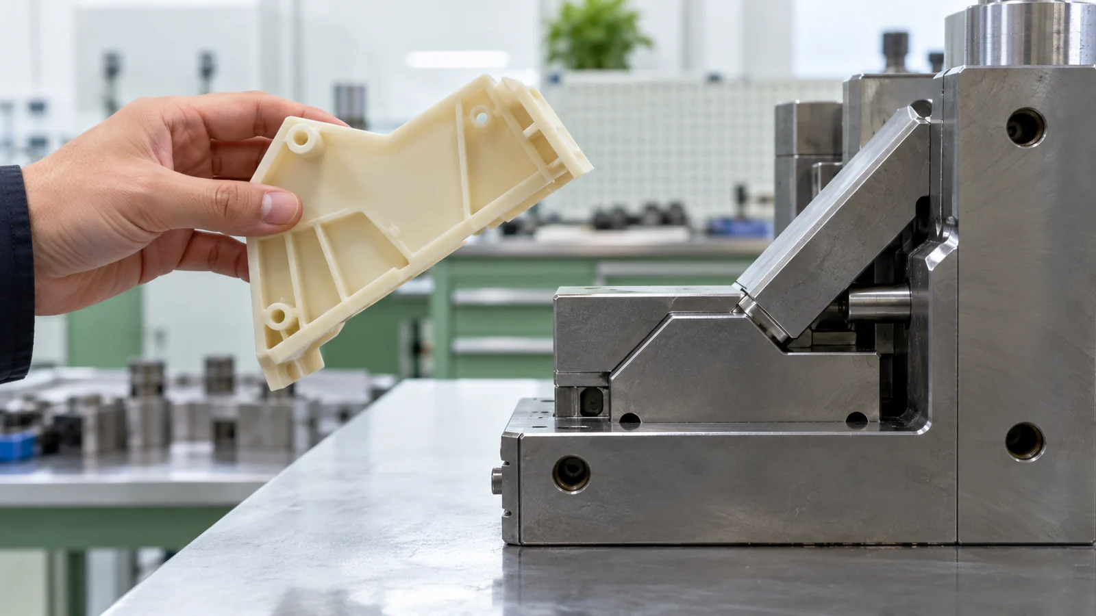
Check head contact area, guide length, support at full extension, and clearance to adjacent ejectors. Shrinkage can tighten the part around the steel; texture can also change release. A CAD animation helps expose collisions but does not prove that the molded part will eject without damage.
What failures point to a lifter design issue?
Scuffing on the undercut may indicate insufficient clearance, draft, or a path that drags across the surface. A cracked feature can point to excessive retention or unsupported ejection. Galling or wear on the lifter may signal poor guidance, contamination, heat, or limited service access. Increasing ejection force before locating the contact point can make damage worse.
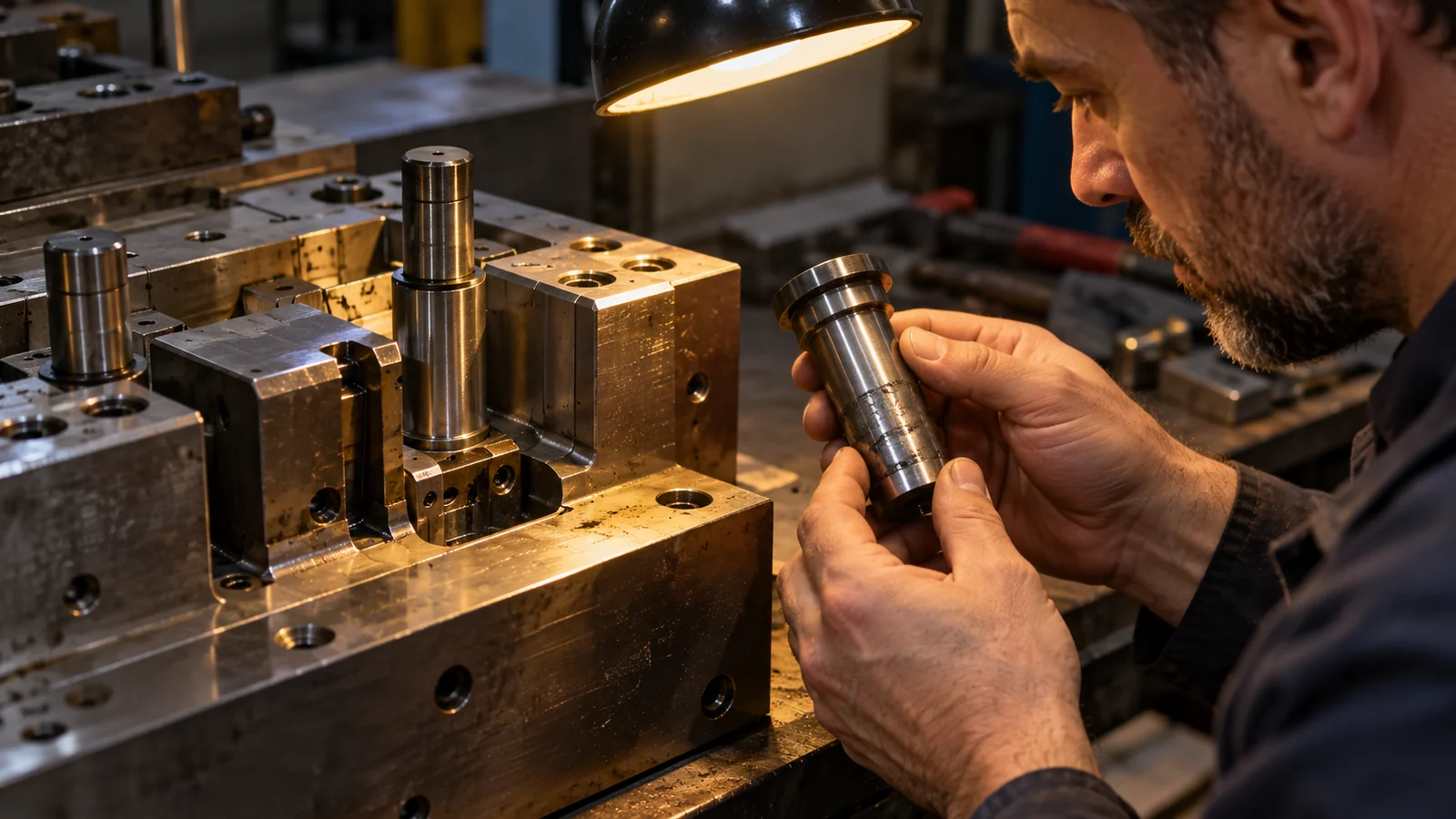
When parts stick, compare the feature with the site’s draft-angle and ejection guidance. Record where the mark appears and in which direction it runs; this helps separate a motion problem from shrink fit or surface friction.
What should be checked before mold release?
- Show the undercut, draft, stroke, and release vector in section.
- Confirm support and clearance at both ends of ejection.
- Define acceptable witness marks and cosmetic limits.
- Review resin, shrink behavior, and surface texture.
- Plan inspection, lubrication, and access to moving components.
Ask the toolmaker to walk through the sequence against the actual part and mold layout. A lifter that clears nominal CAD geometry but cannot be supported or serviced in the production tool is not a complete solution.
Questions buyers ask about injection mold lifters
Can a lifter form every internal undercut?
No. Depth, direction, feature strength, available travel, and mold space set the limits. Deep or side-facing features may need another mechanism or part revision.
Will a lifter leave a mark?
It can leave a witness or contact mark depending on location, fit, finish, and ejection load. Define cosmetic zones and acceptance criteria before tooling.
Can more draft eliminate the lifter?
Sometimes, if the release geometry can change without harming assembly or function. Review the complete part before removing the undercut.