
Cooling-channel design is not just a matter of drilling the closest possible path to the cavity. Channel location, spacing, diameter, circuit length, steel thickness, and access all influence how evenly the mold removes heat—and whether the tool can be made and maintained safely. A useful review compares the channel layout with the part’s thick sections, likely hot spots, and the surrounding mold structure.
This article focuses on conventional injection mold cooling layout. It is distinct from optimizing cooling time alone; the first task is to design a practical thermal circuit that supports repeatable parts. The broader custom mold making plan should review cooling with gates, ejectors, slides, and steel strength.
In this guide:
- Map the part’s thermal needs
- Choose channel layout
- Account for manufacturability
- Validate the circuit
- FAQ
How should the part guide cooling-channel layout?
Start with wall thickness, ribs, bosses, cores, and areas that retain heat. A uniform-looking surface can hide uneven thermal mass: a thick boss may cool slower than the adjacent wall, pulling the part or extending the time before ejection. Map these features against the cavity and core rather than placing channels from a top-down view only.
Review both mold halves and consider the part’s release and dimensional requirements. Channels too far from a thick section may leave a local hot spot; channels too close can reduce steel strength or risk breakthrough. The correct offset depends on the tool material, geometry, drilling limits, pressure, and required service life—there is no single spacing rule that fits every mold.
Which cooling circuit arrangement fits the geometry?
Straight drilled circuits are practical for accessible, relatively simple regions. Baffles or bubblers can direct coolant into deep cores, but they add flow restrictions and assembly details. Complex geometries may require multiple independent circuits so the flow and temperature can be balanced by region. Keep connections accessible and label circuit paths in the mold documentation.
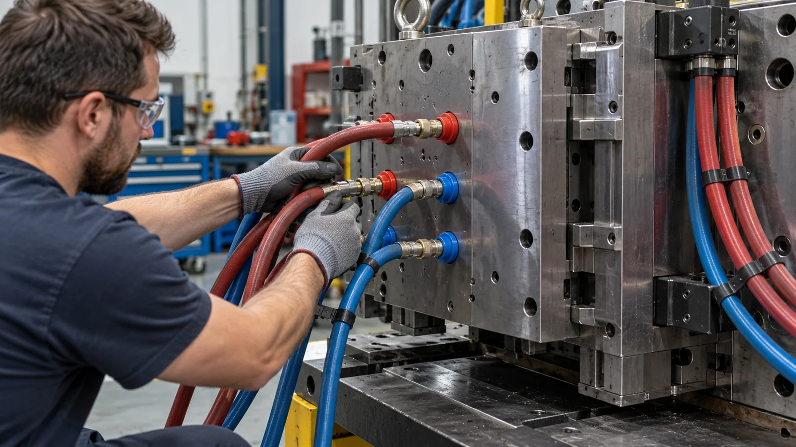
Think about circuit length, bends, parallel paths, and pressure drop. A long circuit can experience a temperature rise along its path, while poorly matched parallel paths may distribute flow unevenly. More circuits are not automatically better if they are difficult to connect, identify, clean, or monitor. The layout should make maintenance understandable for the production team.
What design constraints can undermine cooling?
Cooling channels compete for space with ejector pins, screws, inserts, slides, lifters, and the part’s functional features. Check minimum steel around channels and intersections, as well as access for drilling, plugging, and repair. Blind or intersecting passages can trap debris or complicate cleaning. A circuit that cannot be flushed reliably may lose performance over time.
Material and finish matter as well. Corrosion, scale, or contamination can reduce flow; coolant treatment and maintenance therefore belong in the production plan. Do not promise a specific cycle-time reduction from a channel drawing alone—molding trials must confirm the result under the intended resin and process conditions.
How can a cooling design be validated?
Review the drawing for channel dimensions, circuit connections, and clearances before machining. During mold trials, record inlet and outlet temperatures and flow conditions by circuit, then compare part dimensions, warpage, surface condition, and ejection behavior across repeated cycles. If one area remains hot, determine whether the cause is the circuit, flow balance, resin behavior, or process setup before changing steel.
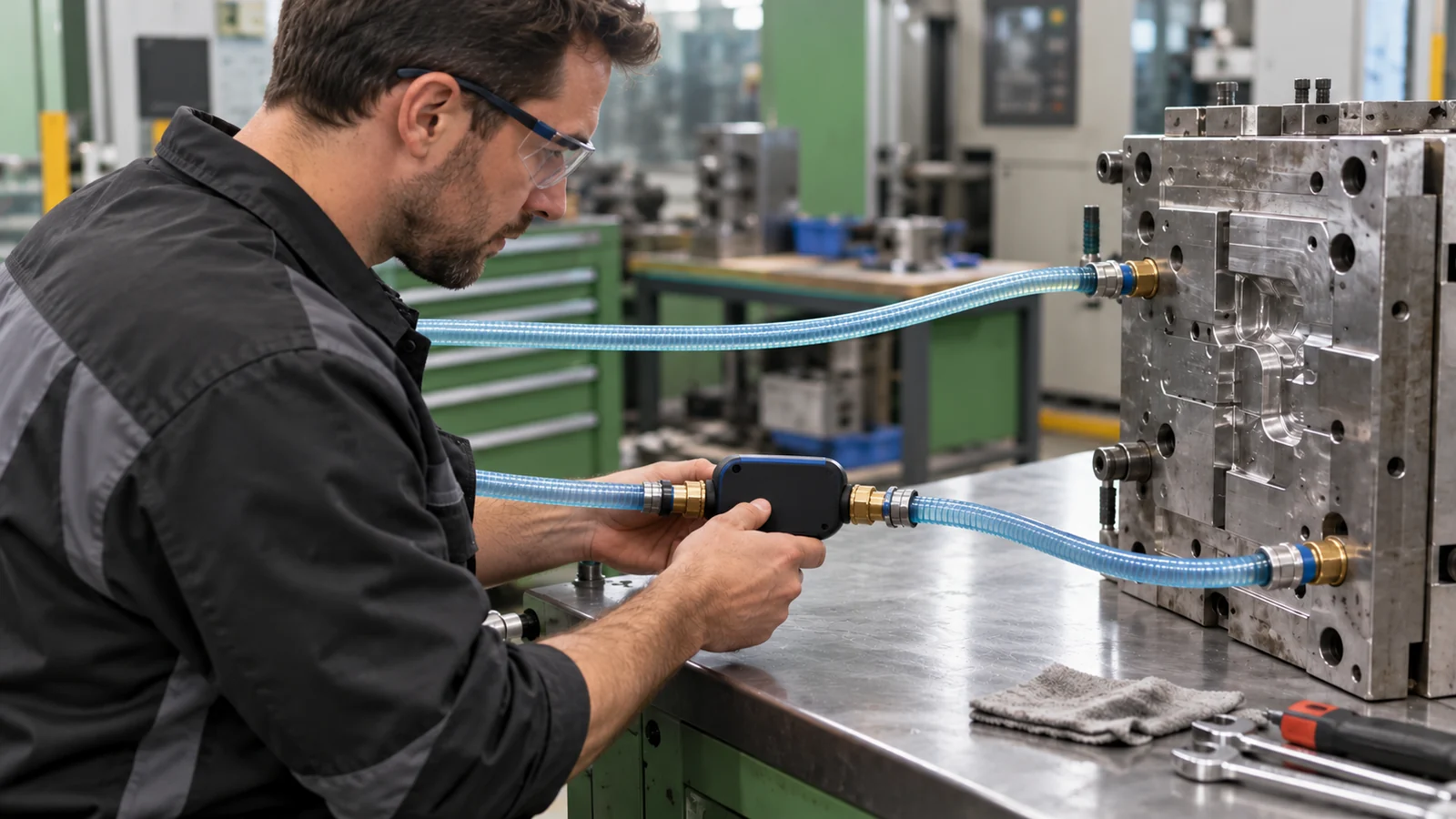
- Trace each circuit from inlet to outlet and confirm labels match the tool documentation.
- Check for leaks and verify flow through each branch.
- Compare cavity and core temperatures near critical regions.
- Measure parts after a repeatable stabilization period.
- Record any circuit restriction, scale, or maintenance issue for follow-up.
For cycle-time decisions, compare those observations with the site’s cooling-time review. The channel design and the process window need to support the same dimensional and release targets.
Questions buyers ask about mold cooling channels
Should channels be as close to the cavity as possible?
No. Proximity must be balanced against steel strength, manufacturing access, pressure, and the local geometry. The design should be checked in section.
Does conformal cooling always outperform drilled channels?
No. It may help with complex shapes, but feasibility, tooling route, cost, cleaning, and validation matter. Conventional circuits can be the more practical solution.
Can cooling channels fix warpage?
They can help address uneven heat removal, but warpage also depends on part geometry, material, packing, gate location, and restraint. Diagnose the full molding system.