
An injection mold lifter is useful when an internal undercut blocks ejection but can clear through a controlled angled movement. It is not simply a smaller side slide: the lifter travels with the ejector system, so its motion, part contact, and timing must work together. Review the feature within the whole 맞춤형 금형 설계 before choosing the mechanism.
Start with the trapped surface and draw its release path. If redesign, an open slot, or a parting-line change preserves function, those options may reduce moving steel and maintenance. Use a lifter when the feature justifies its added motion.
이 가이드에서:
When is a lifter a better fit than a slide?
A lifter is considered for an internal undercut that can move diagonally away from the molded feature during ejection. A straight side core is often more direct when the feature needs dedicated lateral withdrawal. Geometry, travel, and mold layout decide; neither mechanism is a universal default.
Undercut depth, draft, wall thickness, ejection direction, and nearby ribs determine whether the lifter can clear without dragging. Deep features may require excessive travel or leave the lifter too slender to remain rigid. Review the part in section as well as in the full mold assembly.
How should lifter movement be coordinated?
The ejector plate drives the lifter forward while its guide path creates lateral displacement. The part must stay supported as the undercut clears. Otherwise, the feature can flex, whiten, crack, or remain caught. Show the full motion and confirm that the lifter clears before handling or robot takeout.
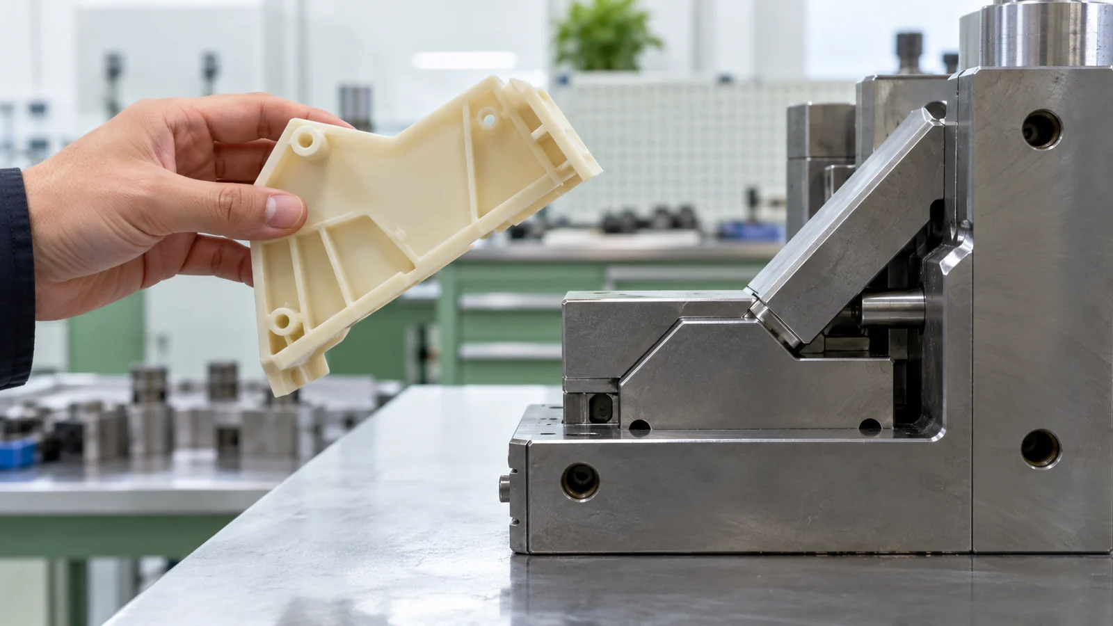
Check head contact area, guide length, support at full extension, and clearance to adjacent ejectors. Shrinkage can tighten the part around the steel; texture can also change release. A CAD animation helps expose collisions but does not prove that the molded part will eject without damage.
어떤 실패가 리프터 설계 문제를 시사합니까?
언더컷의 스커핑은 간극, 구배 또는 표면을 끌고 지나가는 경로가 불충분함을 나타낼 수 있습니다. 피처의 균열은 과도한 유지력 또는 지지되지 않은 이젝션을 시사할 수 있습니다. 리프터의 갈링 또는 마모는 불량한 가이드, 오염, 열 또는 제한된 정비 접근성을 신호할 수 있습니다. 접촉점을 찾기 전에 이젝션 힘을 높이면 손상이 악화될 수 있습니다.
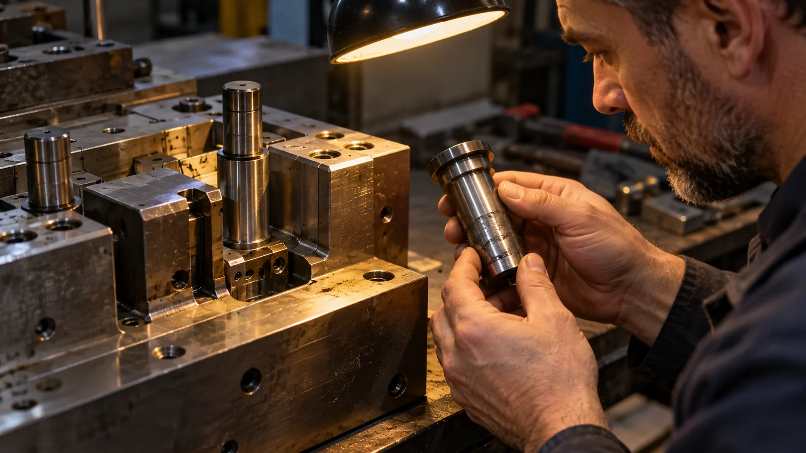
부품이 달라붙을 때는 해당 피처를 사이트의 구배 각도 및 이젝션 지침. 과 비교하십시오. 자국이 나타나는 위치와 진행 방향을 기록하십시오. 이는 운동 문제와 수축 끼워맞춤 또는 표면 마찰을 구분하는 데 도움이 됩니다.
금형 이형 전에 무엇을 확인해야 합니까?
- 단면에서 언더컷, 구배, 스트로크 및 이형 벡터를 표시하십시오.
- 이젝션 양단에서 지지와 간극을 확인하십시오.
- 허용 가능한 위트니스 마크와 외관 한계를 정의하십시오.
- 수지, 수축 거동 및 표면 질감을 검토하십시오.
- 검사, 윤활 및 이동 부품에 대한 접근을 계획하십시오.
툴메이커에게 실제 부품 및 금형 레이아웃에 대조하여 시퀀스를 검토해 달라고 요청하십시오. 공칭 CAD 형상을 통과하지만 생산 금형에서 지지되거나 정비될 수 없는 리프터는 완전한 솔루션이 아닙니다.
구매자가 사출 금형 리프터에 대해 묻는 질문
리프터가 모든 내부 언더컷을 성형할 수 있습니까?
아니요. 깊이, 방향, 피처 강도, 사용 가능한 이동 거리 및 금형 공간이 한계를 설정합니다. 깊거나 측면을 향한 피처는 다른 메커니즘 또는 부품 수정이 필요할 수 있습니다.
리프터가 자국을 남기나요?
위치, 맞춤, 마감, 이젝션 하중에 따라 흔적 또는 접촉 자국을 남길 수 있습니다. 툴링 전에 외관 구역과 합격 기준을 정의하십시오.
드래프트를 더 늘리면 리프터를 없앨 수 있나요?
조립이나 기능에 영향을 주지 않고 이형 형상을 변경할 수 있다면 때때로 가능합니다. 언더컷을 제거하기 전에 전체 부품을 검토하십시오.