
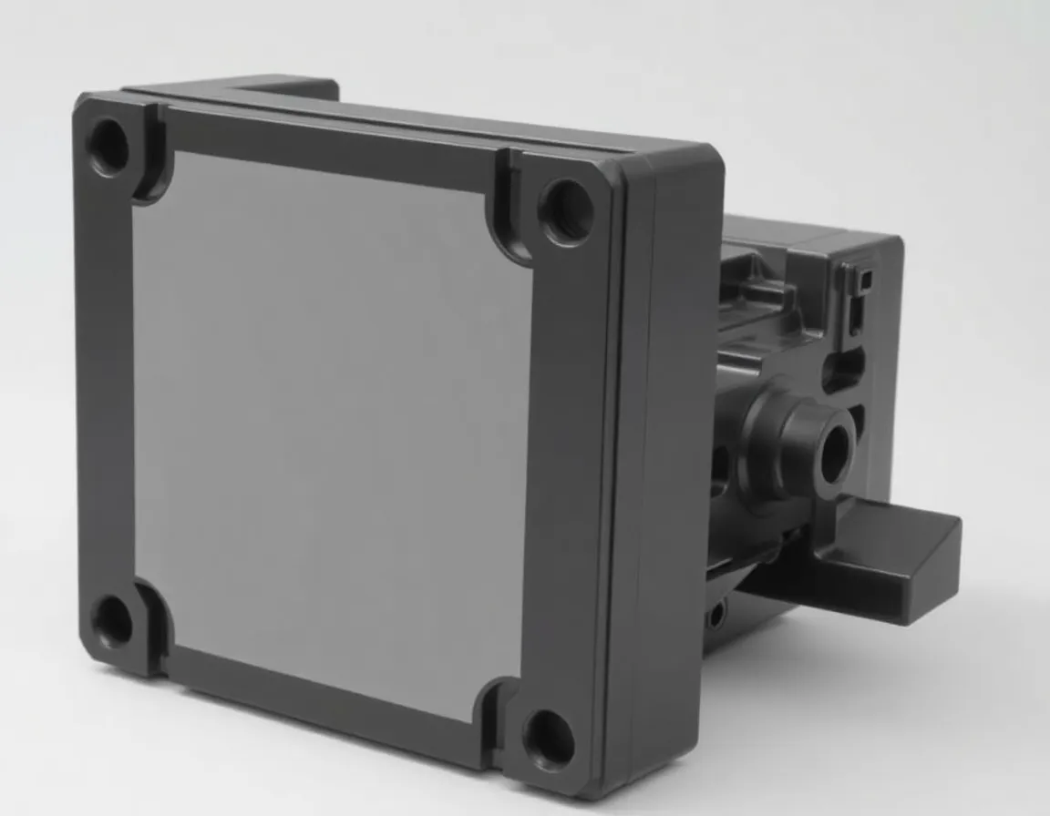
Introduction: The Critical Role of Precision in Telecommunications Enclosures
The telecommunications industry is the invisible backbone of the modern world, facilitating everything from a simple mobile phone call to the complex data streams that power global financial markets. Within this intricate ecosystem, the humble plastic enclosure plays a role far more critical than mere packaging. It is the protective armor for sensitive electronics, the thermal management system, and often the first line of defense against electromagnetic interference (EMI). As 5G, IoT, and edge computing drive demand for smaller, more powerful, and more durable devices, the process of telecommunication plastic enclosure molding has evolved from a basic manufacturing step into a high-precision engineering discipline. A poorly molded enclosure can lead to signal degradation, overheating, and catastrophic device failure. This article unveils the five professional secrets that separate world-class molding operations from average ones, ensuring that your enclosures meet the rigorous demands of the telecom sector.
Secret #1: Mastering Material Selection for High-Frequency Performance
The first, and arguably most important, secret to perfect plastic enclosure molding is not about the machine, but about the polymer chemistry. In telecommunications, the enclosure is not an inert shell; it is an active participant in the device’s RF (Radio Frequency) performance. Using the wrong material can absorb signal strength, detune antennas, or cause unintended resonance.
Understanding the Dielectric Constant (Dk) and Dissipation Factor (Df)
For high-frequency applications (above 1 GHz), the material’s Dielectric Constant (Dk) and Dissipation Factor (Df) are non-negotiable. A low Dk ensures that the plastic does not store electrical energy, which slows down signal propagation. A low Df ensures that the material does not convert electrical energy into heat, which causes signal loss. Standard ABS or PC/ABS blends, while strong, often have poor high-frequency characteristics. Instead, professionals turn to specialized compounds:
- LCP (Liquid Crystal Polymer): Excellent for high-frequency due to low Dk, but can be anisotropic (properties vary by direction).
- PPE/PPO (Polyphenylene Ether/Oxide): Offers a good balance of low moisture absorption and stable Dk across a wide temperature range.
- PPS (Polyphenylene Sulfide): High-temperature resistance and excellent chemical resistance, often used with glass fiber reinforcement.
- Modified PTFE compounds: The ultimate low-loss option, but expensive and difficult to mold.
The Role of Fillers and Flame Retardants
Telecom equipment often sits in confined spaces with high heat generation. Therefore, flame retardancy (UL 94 V-0 rating) is mandatory. However, halogenated flame retardants can impact Dk. Modern molding experts use halogen-free flame retardants combined with mineral fillers. These fillers not only reduce cost but also lower the Coefficient of Thermal Expansion (CTE), preventing warpage when soldering connectors or mounting PCBs. The secret is to balance the mechanical strength required for drop tests with the electrical clarity required for signal integrity. Never select a material based solely on datasheet values; always request in-mold test plaques to verify RF performance under real molding pressures and temperatures.
Secret #2: Optimizing Mold Design for Wall Thickness and Flow
Once the material is selected, the geometry of the mold becomes the battleground for perfection. In telecom enclosures, which often feature complex internal ribbing for mounting PCBs and heat sinks, the flow of molten plastic is the primary challenge. The secret here is balanced filling and uniform wall thickness.
Avoiding Sink Marks and Voids
Sink marks are the bane of cosmetic quality, but in telecom, they are also a structural weakness. They occur when thick sections (e.g., mounting bosses) cool slower than thin walls, causing shrinkage on the surface. The professional solution is conformal cooling channels within the mold. Unlike straight-line drilled cooling lines, conformal channels follow the contour of the part using 3D-printed mold inserts. This ensures rapid, uniform cooling, reducing cycle time and preventing differential shrinkage.
Gate Placement and Weld Lines
The gate is where the plastic enters the cavity. In a telecom enclosure, a poorly placed gate can create a weld line—a weak point where two flow fronts meet. If a weld line occurs near a critical mounting hole or an antenna feed point, it can cause mechanical failure or RF leakage. Professionals use Moldflow Analysis (CAE) software to simulate the filling process. The secret is to place gates to push weld lines to non-critical areas or to use overflow wells (small cavities that capture the cold front of the plastic) to eliminate the weld line entirely. For large enclosures, consider sequential valve gating where multiple gates open and close in a controlled sequence to manage weld line placement and reduce injection pressure.
Secret #3: Controlling the Injection Molding Process Parameters
Even the best mold and material will fail if the injection molding machine is not tuned like a fine instrument. The secret to perfect telecommunication plastic enclosure molding lies in the process window—the specific range of temperatures, pressures, and speeds that yield a consistent, stress-free part.
The Importance of Viscosity and Shear Heat
Telecom materials like LCP and PPS are highly shear-sensitive. If the injection speed is too high, the material degrades due to frictional heat, creating black specks or "burn marks." If it is too slow, the material freezes prematurely, leading to short shots. The professional approach is to use a profiled injection speed. Start slow to allow the plastic to pass through the gate without jetting, accelerate to fill the main cavity quickly, then decelerate at the end to pack out the part without over-packing the gate.
Packing Pressure and Holding Time
Packing pressure is what pushes the plastic into the mold to compensate for shrinkage as it cools. For a telecom enclosure with tight dimensional tolerances (often ±0.05mm for connector fit), the packing profile is critical. Too little packing leads to sink marks; too much leads to flash (thin plastic fins) around the parting line, which can break off and cause short circuits. The secret is to use a two-stage packing profile: a high initial pressure to "pack" the part, followed by a lower holding pressure to maintain contact without over-stressing the mold. This minimizes internal stress, which is crucial because stressed plastic can warp when exposed to the heat of a soldering process or an outdoor environment.
Mold Temperature Control
Unlike commodity molding, telecom molding often requires high mold temperatures (80°C to 140°C). This is not just for cosmetic gloss; it ensures that the polymer chains have time to relax, reducing molecular orientation and internal stress. For high-performance materials, consider using a variotherm process (rapid heating and cooling of the mold surface) to achieve a flawless surface finish without increasing cycle time significantly.
Secret #4: Implementing Rigorous Quality Assurance and In-Process Inspection
Perfect molding is not just about making the part; it is about proving it is perfect. In the telecommunications industry, a single batch of defective enclosures can halt production of a base station or a network router, costing millions. The secret to success is a closed-loop quality system that monitors every cycle.
Using Automated Vision Systems
Manual inspection is no longer viable for high-volume production. Professionals integrate inline automated optical inspection (AOI) systems directly into the molding cell. These cameras check for surface defects, flash, sink marks, and color consistency in milliseconds. More advanced systems use X-ray inspection for internal voids that are invisible to the naked eye.
Dimensional Accuracy and CMM
The critical dimensions of a telecom enclosure (e.g., the distance between mounting bosses, the depth of the PCB recess) must be verified. While a Coordinate Measuring Machine (CMM) is used for first-article inspection, the secret to continuous production is using in-mold sensors (pressure and temperature transducers). These sensors provide real-time data on cavity pressure. If the pressure deviates from the established "golden profile," the machine automatically rejects the part. This is called Statistical Process Control (SPC). By tracking the cavity pressure curve, you can predict mold wear and material batch variations before they create defective parts.
Testing for EMI Shielding
Many telecom enclosures require EMI shielding. Often, this is achieved by plating the inside of the plastic (electroless copper/nickel) or using conductive gaskets. However, the molding process affects the adhesion of these layers. The secret is to test the surface energy of the molded part (using dyne pens) before sending it to the plating line. If the molding process leaves mold release agents on the surface, the plating will peel. Therefore, professionals use internal mold release agents (compounded into the resin) rather than external sprays, ensuring consistent adhesion.
Secret #5: Post-Molding Handling and Secondary Operations
The molding process does not end when the part is ejected. The final secret to perfection lies in how the part is handled, degated, and finished. Telecom enclosures are often large and thin-walled, making them prone to warpage if not handled correctly immediately after ejection.
The Cooling Fixture
As the part exits the mold, it is still hot and soft. If it is dropped onto a conveyor belt or into a gaylord box, it will deform. The professional secret is to use a custom cooling fixture that holds the part in its exact final dimensions while it cools to ambient temperature. This is called "fixture cooling" and is essential for maintaining flatness tolerances on large covers and base plates.
Robotic Degating and Deflashing
Manual degating (removing the sprue and runners) introduces human error and can scratch the surface. Using a 6-axis robotic arm to remove the part from the mold, separate the runner, and place the part in the cooling fixture is the industry best practice. The robot can also perform in-process deflashing using a small brush or cryogenic process if flash is present.
Ultrasonic Welding and Insert Molding
Many telecom enclosures consist of two halves (top and bottom) that need to be joined to create a sealed, dust-proof and water-resistant unit (e.g., IP65 rating). While screws are common, ultrasonic welding offers a cleaner, more secure seal. The secret to perfect welding is ensuring the energy director (a triangular ridge on one half) is molded perfectly. If the molding process leaves sink marks on this ridge, the weld will be weak. Additionally, consider insert molding for brass threaded inserts. This involves placing the metal insert into the mold before injection. This provides a much stronger connection than heat-staking and eliminates the risk of cracking the plastic during assembly.
Packaging and Cleanliness
Finally, the packaging must be anti-static and dust-free. Telecom electronics are sensitive to electrostatic discharge (ESD). The molded plastic, if not treated, can generate static electricity. The secret is to use anti-static additives in the resin or to treat the parts with a topical anti-static spray after molding. Parts must be individually wrapped or separated with foam to prevent scratches during transit. For medical-grade or high-end telecom, consider molding in a cleanroom environment to prevent dust particles from embedding in the surface.
Conclusion: The Synergy of Science and Experience
Perfect telecommunication plastic enclosure molding is not achieved by accident. It is the result of a meticulous synergy between advanced polymer science, precision tooling, data-driven process control, and rigorous post-processing. The five secrets outlined—material selection, mold design, process parameter optimization, in-process quality assurance, and careful handling—are the pillars upon which reliable network infrastructure is built. By mastering these areas, manufacturers can produce enclosures that not only look pristine but also perform flawlessly under the heat, humidity, and electromagnetic stress of the real world. As the industry moves toward higher frequencies (6G) and more compact designs, these secrets will become even more critical. The manufacturers who invest in this knowledge will not just mold plastic; they will mold the future of global connectivity.