
Robot cable overmolding is most useful at a defined termination or transition—not across the section that must flex and twist through the robot’s motion. A larger molded boot does not automatically reduce cable failures. If it moves the bend point to a short, stiff boundary, the conductor or jacket may still fatigue where the flexible cable exits the overmold. Start by locating the real failure zone and mapping the motion before changing the molded geometry.
Read the failure location first
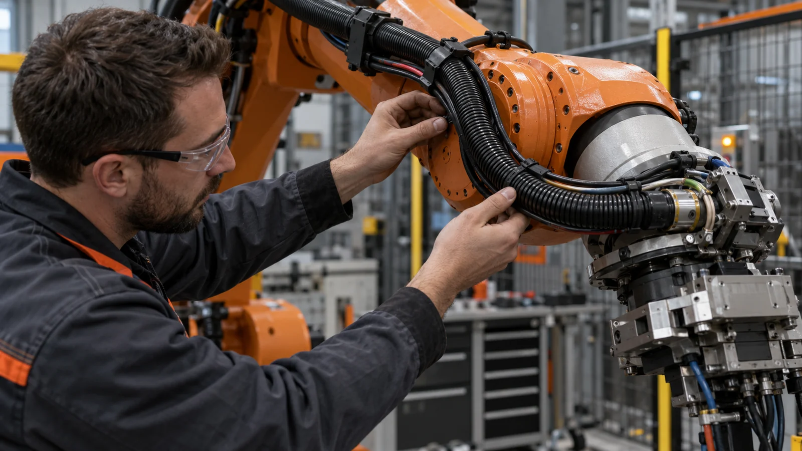
Before redesigning a boot, inspect where the cable fails and how it was installed. A conductor break near the termination, a split in the outer jacket, a pulled connector, and abrasion farther along the arm point to different causes. Record the robot axis, cable path, bend direction, torsion, clamp positions, and whether the failure follows a particular motion or tool orientation.
The molded transition should address the load it actually sees. It may help protect a termination from handling or reduce an abrupt change in support, but it cannot correct an unsuitable cable, excessive travel, collision, or a routing path that repeatedly twists the same segment. Keep cable manufacturer limits for bend and torsion as design inputs; do not infer a universal bend radius from the molded part alone.
Within a 로보틱스 사출 성형 project, scope cable overmolding as a molded component around an identified cable or connector interface. It does not imply that the molding supplier provides the complete cable harness, conductor termination, electrical test, or robot dress-pack system unless those services are separately confirmed.
Keep the moving cable out of the rigid boundary
The most sensitive region is often the point where a flexible cable leaves a stiff molded boot. If that boundary sits directly at a repeated bend or twist, the transition can concentrate strain instead of distributing it. Draw the cable’s full motion envelope and mark where it is clamped, where it can move, and where it must remain protected.
Use the overmold to support the termination without gripping the cable so aggressively that it creates a new stress concentration. A gradual transition may reduce abrupt stiffness changes, but the right length and shape depend on cable construction, jacket material, motion, and surrounding clearance. Confirm the cable can move through the required path without rubbing against the robot link, cover, or neighboring cables.
For the insert-molding step, check whether the cable jacket tolerates the molding temperature, pressure, and resin contact. Shielding, connector geometry, cable position, and any required electrical isolation need to be understood before the tool is finalized. If the design includes a metal terminal or other insert, review the applicable 인서트 사출 성형 considerations alongside the overmold.
Design the molded transition around the cable
유지력은 접착, 성형된 형상 또는 이들의 조합에서 나올 수 있지만, 케이블 재킷과 종단부에 맞아야 합니다. 오버몰드가 모든 재킷에 화학적으로 접합될 것이라고 가정하지 마십시오. 인발에 저항하기 위해 기계적 스톱, 커넥터 숄더 또는 포획 형상이 필요할 수 있으며, 반면에 잘못 배치된 날카로운 모서리는 굽힘 중에 재킷을 손상시킬 수 있습니다.
케이블을 압착하거나 변형시키지 않는 안정적인 위치 결정 형상으로 금형 내 케이블의 위치를 정의하십시오. 셧오프는 재킷을 절단하지 않으면서 플래시를 제어해야 합니다. 인서트 주변으로 갇힌 공기가 어떻게 빠져나가는지, 그리고 중요한 위치를 흐트러뜨리지 않고 케이블을 어떻게 장입하고 제거할 수 있는지 고려하십시오. 반복 가능한 공정은 단지 CAD에서 올바르게 보이는 캐비티가 아니라 케이블이 일관되게 제시되는 것에 달려 있습니다.
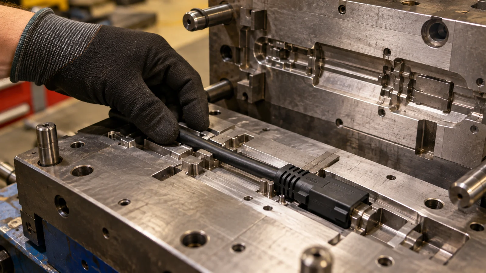
수지와 케이블 구성을 함께 지정하십시오. 호환성, 온도 노출, 유연성, 화학적 접촉, 그리고 요구되는 색상 또는 식별 모두가 선택에 영향을 미칩니다. 재료와 형상은 하나의 인터페이스로 검토되어야 하며, “스트레인 릴리프”라는 라벨은 성능 사양이 아닙니다.
Test the complete routed assembly
인발 시험은 유지력 약점을 드러낼 수 있지만, 로봇 운동을 대표하지는 않습니다. 검증에는 의도된 케이블, 커넥터, 성형 전이부, 라우팅 하드웨어 및 운동 시퀀스를 사용해야 합니다. 축방향 인발을 통과한 부트라도 전이부에서 반복적인 굽힘 하에서는 여전히 실패할 수 있습니다.
- 기준선을 문서화하십시오: 라우팅을 촬영하고 관찰된 실패 위치를 표시하십시오.
- 설치를 확인하십시오: 커넥터 체결, 케이블 클램프 및 사용 가능한 여유를 확인하십시오.
- 대표적인 운동을 실행하십시오: 굽힘 또는 비틀림을 일으키는 로봇 축과 공구 방향을 포함하십시오.
- 사이클링 후 검사하십시오: 재킷 백화, 균열, 인발, 마모 또는 도체 연속성 변화를 찾으십시오.
- 서비스 노출 후 반복하십시오: 사용의 일부인 경우 실제 온도, 세정제, 오일 또는 취급 조건을 추가하십시오.
시험 전에 합격 기준을 설정하십시오: 무엇이 재킷 손상으로 간주되는지, 종단부에서 허용되는 움직임, 그리고 연속성 또는 신호 성능이 측정되는지 여부입니다. 외관 검사만 통과하는 것으로는 전기적 무결성을 확인할 수 없습니다.
| 관찰된 문제 | 검사할 첫 번째 영역 | 수집할 증거 |
|---|---|---|
| 성형된 출구 근처의 파손 | 강성 전이 및 반복 굽힘 지점 | 운동 경로 및 굽힘 위치 |
| 부트가 케이블 위에서 움직임 | 재킷 호환성 및 유지 형상 | 인장 시험 및 사이클 후 움직임 |
| 경로 더 아래쪽의 재킷 긁힘 | 간극, 클램프 위치 및 마찰 표면 | 전체 조립 경로 및 마모 흔적 |
Know when a separate guide is better
오버몰딩은 종단부에 일체형 보호 전이부가 필요할 때 적합합니다. 이는 움직이는 케이블을 암을 따라 배선하는 것과 같지 않습니다. 별도의 클립이나 캐리어가 경로를 제어하고 간극을 유지할 수 있으며, 성형된 부트는 국부적인 출구만 보호합니다. 일부 설계는 둘 다 필요로 하고, 다른 설계는 성형 특징부를 고려하기 전에 다른 케이블이나 배선 전략이 필요합니다.
몰딩 검토를 위해서는 케이블 및 재킷 사양, 커넥터 도면, 요구되는 움직임, 설치 순서, 환경, 그리고 관찰된 고장 증거를 제공하십시오. 이는 막연히 “더 강한 스트레인 릴리프”를 요청하는 것보다 더 유용합니다.”
FAQ
오버몰딩이 로봇 케이블의 파손을 막을 수 있습니까?
종단부의 지지를 개선할 수는 있지만 모든 피로 원인을 해결할 수는 없습니다. 파손이 굽힘, 비틀림, 마모, 인발 또는 부적합한 케이블에서 비롯되는지 식별하고 전체 경로를 검증하십시오.
성형 수지가 케이블 재킷에 접합됩니까?
반드시 그렇지는 않습니다. 접착은 정확한 재킷 및 몰딩 재료에 따라 달라집니다. 호환성을 확인하고 인터페이스에 필요할 경우 기계적 고정을 사용하십시오.
부트가 케이블의 움직이는 부분을 덮어야 합니까?
일반적으로 설계는 활성 굽힘 영역을 고정하기보다는 케이블의 필요한 유연성을 유지해야 합니다. 몰딩 경계를 정의하기 전에 움직임을 매핑하고 케이블 공급업체의 한계를 따르십시오.