
Plastic micro molding is an umbrella term for projects in which tiny shot size, microfeatures, or sub-millimeter handling changes the normal molding strategy. The label alone does not tell a buyer which equipment, tool architecture, material, or inspection method is appropriate. Two “micro” parts can require very different development routes.
This guide separates the common project types, shows what changes at small scale, and helps decide when micro molding offers a real advantage over standard precision molding or another manufacturing process.
Fast classification: determine whether the project is driven mainly by small shot volume, a microfeature, or a sub-millimeter finished component. More than one can apply.
目次
When Small Size Actually Changes the Process

Small dimensions reduce thermal and mechanical margins. Thin flow paths can freeze quickly. A tiny vent blockage can trap a meaningful gas volume. Ejector contact may occupy a large percentage of the part. Static and air movement can control collection. Measurement uncertainty can consume much of a tolerance.
Shot size is equally important. The machine must meter and deliver a repeatable amount without subjecting material to excessive residence. A large runner feeding a tiny component may waste material and complicate thermal history. Gate and runner decisions therefore affect both economics and process stability.
Scale also changes communication. A drawing should define magnification, datum, conditioning, allowable flash, gate vestige, and handling marks. Terms such as “burr-free” or “perfect replication” need measurable acceptance criteria.
Three Project Types Hide Under One Term
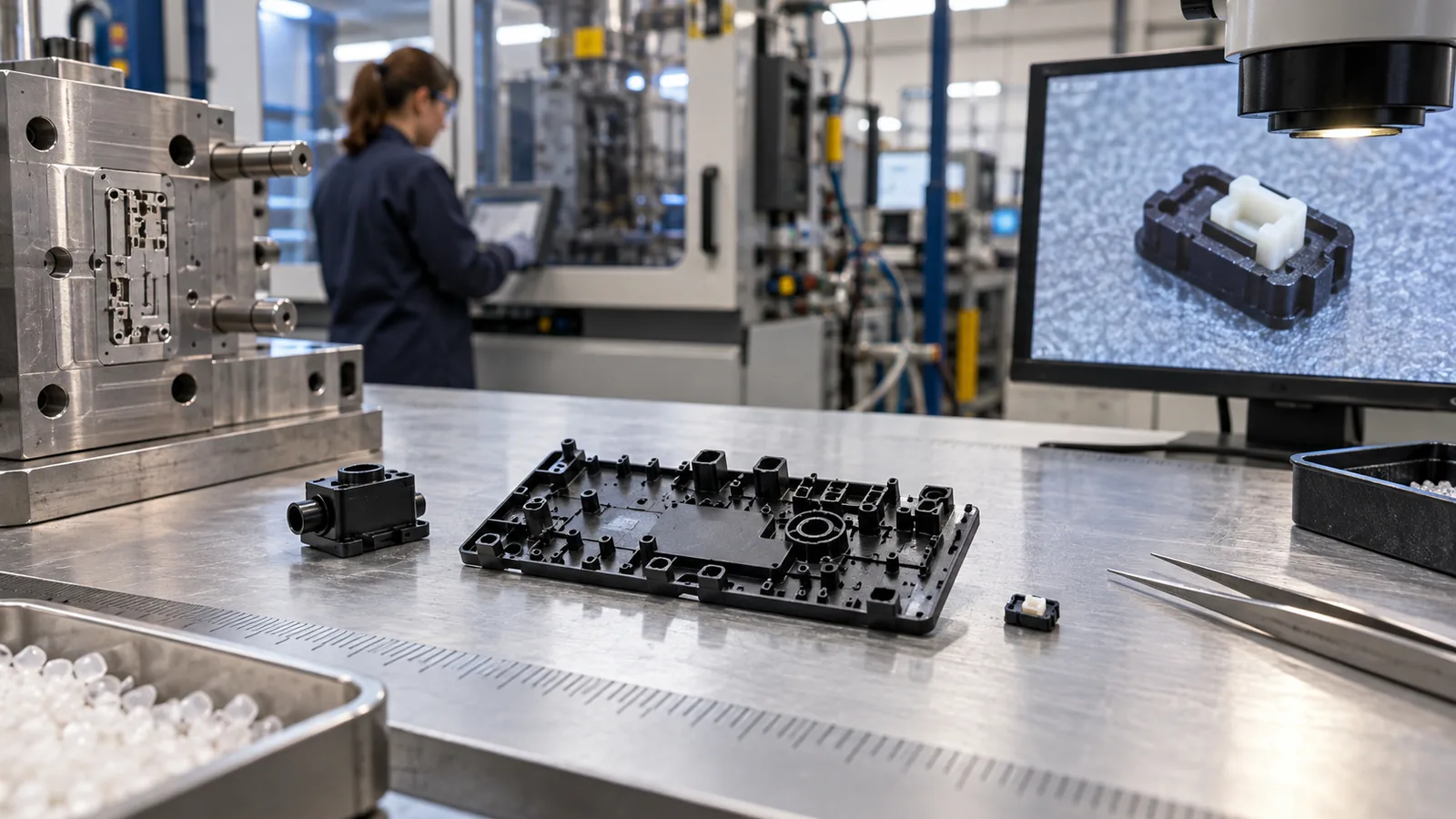
| Project type | Dominant challenge | Typical evidence |
|---|---|---|
| Small finished part | Metering, release, collection, counting | Shot repeatability and handling trial |
| Larger part with microfeatures | Local replication and tool insert accuracy | Feature profiles by gate distance |
| Micro insert or multi-material part | Position, interface, flash and retention | Interface section and functional pull or seal test |
Classifying the project prevents irrelevant specifications. A part with one microfluidic channel needs a different inspection and surface strategy from a tiny gear. A small housing around a metal terminal adds insert-location and electrical risks that do not exist in a single-material component.
Match the Tooling Route to the Feature
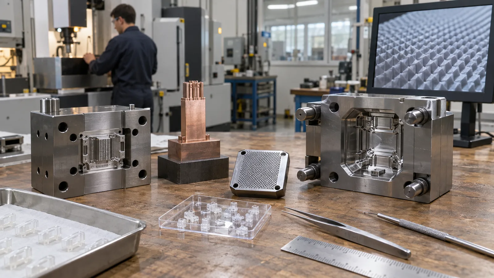
Tooling must create and preserve the critical feature. EDM, precision grinding, micro milling, laser methods, electroforming, or interchangeable inserts may be considered depending on geometry, surface, steel, and maintenance. The correct method is not the smallest available cutter; it is the route that creates the required profile with a maintainable datum chain.
Fragile cores and high-aspect-ratio ribs need support and a replacement plan. Venting must connect the last-fill location to a real exhaust path. Parting lines and shutoffs should keep flash away from sealing, optical, gear, or contact surfaces.
A カスタム金型製作 review should show gate, vent, insert, ejector, cooling, steel-safe, and measurement concepts before tool release.
Balance Material Flow With Final Performance
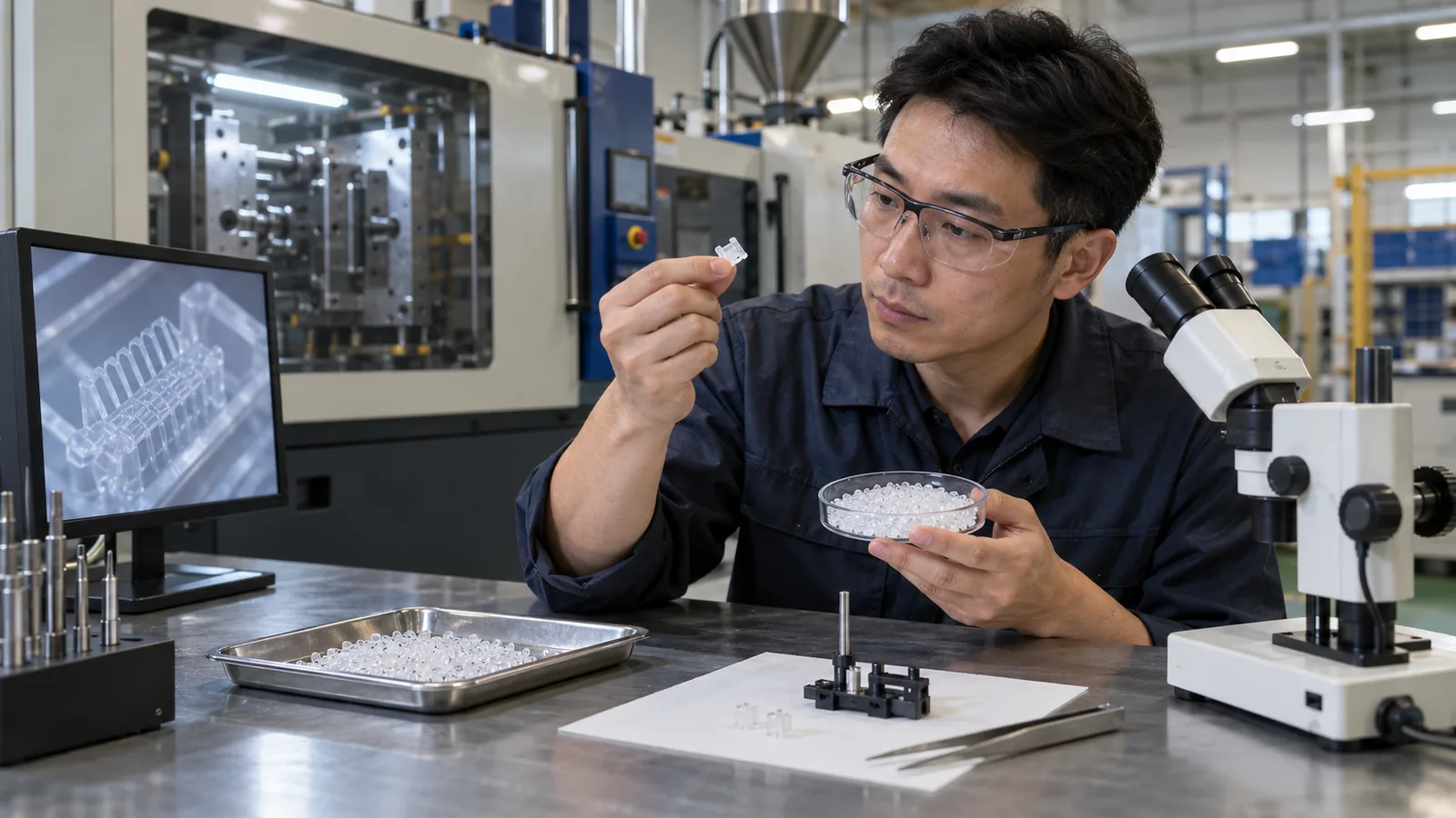
Easy filling does not guarantee a durable part. Material selection must cover the product environment and the molding window. Temperature, chemicals, wear, creep, optics, electrical behavior, sterilization, and biocompatibility can be more important than nominal viscosity.
At the same time, grade-specific flow, filler size, orientation, moisture, degradation, shrinkage, and release determine whether the geometry is practical. Use the exact intended grade and color in qualification. A substitute resin may answer a tooling question but should not be treated as product approval.
サイトの engineering plastics overview is a useful starting point for POM, PA, PBT and related families, while high-temperature or medical applications may require a different material group.
Plan Handling and Inspection Before Production

A molded part has not succeeded if it cannot be removed, counted, inspected, and packaged without damage. Static control, robotic pickup, nests, cavity separation, vision detection, and packaging may need to be designed alongside the mold.
Inspection should target the feature that drives function. Establish the datum, restraint, edge rule, magnification, resolution, conditioning time, and sampling by cavity. A method qualified on a larger, easier feature may not repeat on a translucent micro wall or flexible element.
- Identify allowable tool and handling witness zones.
- Choose a controlled release and pickup sequence.
- Preserve cavity identity where risk requires it.
- Qualify feature-level measurement repeatability.
- Inspect after the actual packaging or conditioning interval.
- Correlate dimensions with assembly and use tests.
Know When Another Process Is the Better Choice
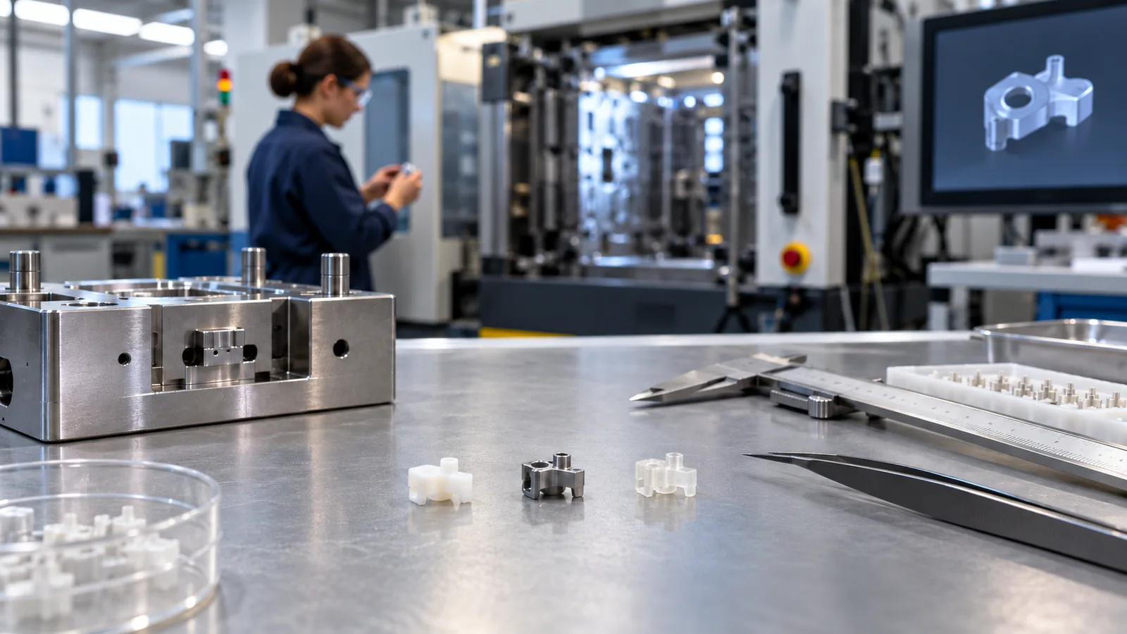
Machining, stamping, laser cutting, additive manufacturing, casting, embossing, or a hybrid assembly may fit early volume or geometry better. Injection molding becomes attractive when the material, repeatability, integrated features, and production volume justify the tooling and process-development effort.
For prototypes, ask what must be learned. Additive parts can verify fit and channel routing, but they do not establish molded shrinkage or gate effects. A prototype mold is more useful when material behavior, release, microfeature replication, or cycle repeatability is the open question.
The dedicated マイクロ射出成形 process fits projects where precision toolmaking, small-shot control, micro-scale ejection, handling, and metrology must operate as one production system.
Before committing to that route, define the production volume, expected tool life, material change policy, inspection cycle, packaging format, and the exact evidence required at each validation stage. Those decisions often reveal the true cost driver more clearly than part weight.
よくある質問
Is plastic micro molding defined by part weight?
No. Shot size is one factor, but microfeatures and sub-millimeter handling can make a larger part a micro-molding project.
Can standard resin data predict feature replication?
Datasheets support screening, but gate distance, tool temperature, geometry, venting, pressure history, and grade formulation require physical validation.
Why is cavity traceability important?
Tool geometry, gate, vent, cooling, and wear can differ by cavity. Traceability prevents a local issue from disappearing in pooled data.
Are all micro parts suitable for multi-cavity tools?
No. Balance, inspection, handling, demand, and cavity-specific capability should be proven before cavity count is increased.
What is the best first feasibility sample?
Use a sample that preserves the hardest functional feature, intended material, realistic gate and vent behavior, and a measurable acceptance method.