
A plastic ultrasonic weld is shaped into the part before it reaches the press. Joint geometry determines where vibration energy concentrates, how the melt is contained, and whether the parts can align and remain supported during collapse. These ultrasonic welding design guidelines help engineers screen a joint before tooling: define the load and sealing need, choose a joint concept, control alignment, and validate the finished assembly rather than relying on appearance alone.
Define what the joint must do before choosing a joint
Start with the assembly’s function: carry a mechanical load, contain a fluid, keep dust out, locate components, or simply retain a cover. A cosmetic bond and a pressure-containing seam do not have the same acceptance criteria. Define the load direction, service environment, expected handling, and whether the seam must be continuous before selecting the joint profile.
Also identify the resin grades, fillers, moisture sensitivity, additives, color, and surface condition of both halves. Nominally similar plastics may weld differently when formulations or reinforcement differ. Material compatibility should be confirmed with the actual grades and production parts, not inferred from a generic polymer family name.
Choose a joint geometry that controls where melt goes
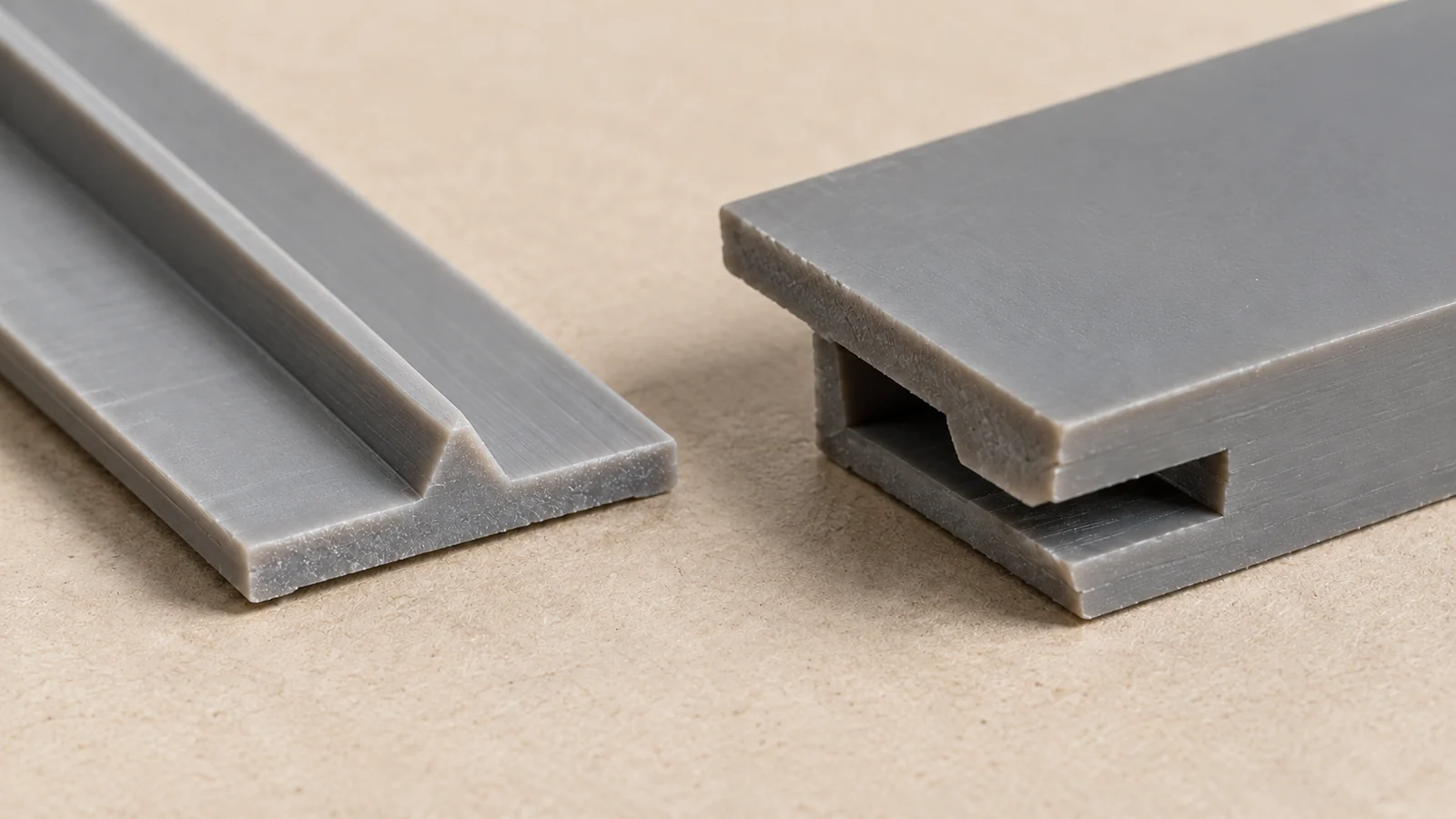
An energy director uses a localized feature to concentrate energy and initiate melting; a shear joint creates controlled interference and progressive contact. Neither is universally best. A simple energy director may suit a straightforward assembly, while a shear-style joint may be considered where a continuous seal or controlled melt path is important. The available wall thickness, access, cosmetic surface, and dimensional tolerances constrain the choice.
Design the joint so molten material has a defined destination. Uncontained flash can mar a show surface, contaminate a functional interface, or make assembly inconsistent. Provide clearance or a flash trap where appropriate, while avoiding thin walls that buckle under clamping. Keep the energy-directing feature continuous where the function requires it, and review interruptions at ribs, corners, bosses, and changes in section.
For a production design, review the proposed joint with the actual ultrasonic welding process and its fixture access. The horn must contact a surface that can transmit vibration without crushing a thin shell or flexing the entire part.
Design for alignment, stiffness, and horn access

Welding pressure can shift or distort poorly located components. Add locating features that bring the halves together in a repeatable position before the weld begins. The fixture should support the part near the joint so the energy is not lost to broad panel flexure. Avoid relying on the horn to correct a mismatch that should be controlled by geometry.
Keep the horn-contact area sufficiently supported and accessible. Ribs, cosmetic curvature, and narrow openings may complicate energy transfer or require a custom horn. A tall unsupported wall can vibrate or collapse away from the seam. Review tolerance stack-up across molded dimensions, assembly locators, and fixture datums; nominal CAD alignment alone does not show whether real parts will seat consistently.
Common design review questions
- Can both halves locate before the joint begins to melt?
- Is the weld land supported by the fixture?
- Can flash escape without reaching a sealing or visible surface?
- Does the horn have clear, repeatable access?
- Will shrinkage or warpage change the contact sequence?
Validate the joint by its required function
A visually closed seam does not prove a weld is strong or leak-tight. Choose tests that reflect the part’s actual job: pull or peel loading, pressure or leak testing, dimensional checks, sectioning, or environmental exposure may be relevant. Define sample locations and acceptance limits before the trial so results can guide a design decision.
During development, record the material lot, part condition, fixture, horn contact, weld sequence, and observed failure location. If a joint fails, determine whether the cause is insufficient fusion, poor alignment, part flex, contamination, or a geometry mismatch. Adjusting machine settings without identifying the failure mode can conceal a weak design rather than fix it.
Where the assembly design is still flexible, compare ultrasonic welding with alternatives such as termosaldatura a punzone only against the same functional requirements and inspection plan.
Domande frequenti
Is an energy director required for ultrasonic welding?
No single joint feature is required for every design. Energy directors are common, but joint type depends on resin, geometry, sealing needs, appearance, and how the assembly can be supported and inspected.
Can ultrasonic welding make a hermetic seal?
A continuous weld can be designed for sealing, but the outcome must be demonstrated with a defined leak or pressure test. Geometry, material, process consistency, and part condition all affect the result.
What should be reviewed before tooling a weld joint?
Review the actual resin grades, joint cross-section, locating features, tolerance stack, horn access, fixture support, flash destination, and functional test. A representative trial should confirm both assembly repeatability and performance.
A reliable ultrasonic joint is a coordinated part, fixture, material, and test design—not simply a machine setting.