
When a molded part costs too much or misses a production target, the cycle-time number is an obvious place to look. But shortening a cycle is useful only if the parts still meet dimensional, cosmetic, and functional requirements. The practical answer is to separate the cycle into its real phases, find which one limits the job, and test changes against stable quality—not to lower temperatures or pull parts early by default.
This guide explains what belongs in the cycle, how tooling and part design influence it, and what buyers should ask a supplier to measure before accepting a proposed reduction.
Respuesta rápida: Total cycle time includes filling, packing and holding, cooling, mold opening, ejection, and closing. Cooling often occupies the largest share, but the limiting step varies by part, resin, tool, and production setup. Reduce the bottleneck in measured increments and track scrap, dimensions, and appearance alongside seconds per cycle.
En este artículo:
- Define the cycle before comparing numbers
- Find the step that actually limits output
- Why cooling is a part-and-tool problem
- Shorten the cycle without creating defects
- What buyers should request in a cycle-time review
- Preguntas frecuentes
Define the cycle before comparing numbers
A cycle-time figure is meaningful only when its start and end points are consistent. A common production measure is the interval from one injection start to the next. That interval may include filling, pack and hold, cooling, screw recovery, mold opening, ejection, part removal, and mold closing. Some machine functions overlap, so adding every displayed timer can overstate the actual cycle.
For a multi-cavity tool, distinguish machine cycle from seconds per part. If the press completes one cycle in 30 seconds and the mold produces four acceptable cavities each shot, the nominal output interval is not 30 seconds per part. Rejects, cavity imbalance, downstream handling, and actual availability still affect good-part rate. A quote or comparison should state whether its number is a target, a trial result, or a sustained production average.
Find the step that actually limits output
Start with a time study on a stable run. Record fill, pack/hold, cooling, screw recovery, mold motion, ejection, and any manual handling separately. Then compare the longest non-overlapping portion with the machine’s actual cycle. The longest visible timer is not automatically the best target: a phase may already overlap another operation, or shortening it may simply move the bottleneck elsewhere.
For example, if the part is dimensionally stable well before the programmed cooling timer ends, cooling may offer a test opportunity. If the part bows during ejection or sticks to the core, the real limit may be stiffness, draft, surface condition, or ejection balance. If the screw has not recovered before the mold is ready to open, plasticizing rather than cooling may be controlling the cycle.
Compare repeated cycles, not the fastest shot in a short sample. Record cavity-by-cavity quality and part weight so that a speed change cannot hide a short shot, poor packing, or an unstable cavity.
Why cooling is a part-and-tool problem

Heat must travel from the polymer through the mold steel and into the coolant. Thick sections, uneven wall transitions, long flow paths, low thermal diffusivity, and poorly balanced circuits can extend the time needed before ejection. Cooling-channel location, diameter, flow, and distance from the cavity matter, but the circuit must also leave enough steel for tool strength and maintenance.
Part geometry is often the first lever. A heavy boss connected to a thin wall can retain heat and create sink or warpage. A more uniform wall and gradual transitions may improve both cooling and filling. Tool changes such as baffles, bubblers, or conformal channels may help in specific geometries, but their benefit should be evaluated against cost, serviceability, and the temperature uniformity actually achieved.
Resin changes the answer too. Amorphous and semi-crystalline materials do not cool and shrink identically, and grade-specific processing guidance matters. Mold temperature is not simply “the colder the better”: an aggressive setting can affect surface replication, residual stress, weld-line strength, or dimensional stability. A structured análisis de flujo de molde can help evaluate filling, packing, and thermal behavior before a tool change, while trials confirm what the physical mold does.
Shorten the cycle without creating defects
Use a controlled sequence rather than changing several settings at once:
- Establish a quality baseline. Save the current process window, part weight, cavity results, key dimensions, appearance criteria, and average cycle.
- Identify the actual constraint. Determine whether cooling, packing, recovery, mold motion, ejection, or handling controls the repeatable cycle.
- Cambie un factor a la vez. Adjust a timer or a defined process variable in small steps while keeping material and other conditions stable.
- Check the failure modes. Inspect for warpage, sink, flash, sticking, short shots, burn marks, gate problems, and dimensional drift—not just whether the part can be ejected.
- Confirm repeatability. Review several consecutive cycles and cavities, then verify the result over a longer stable run before treating it as the production standard.
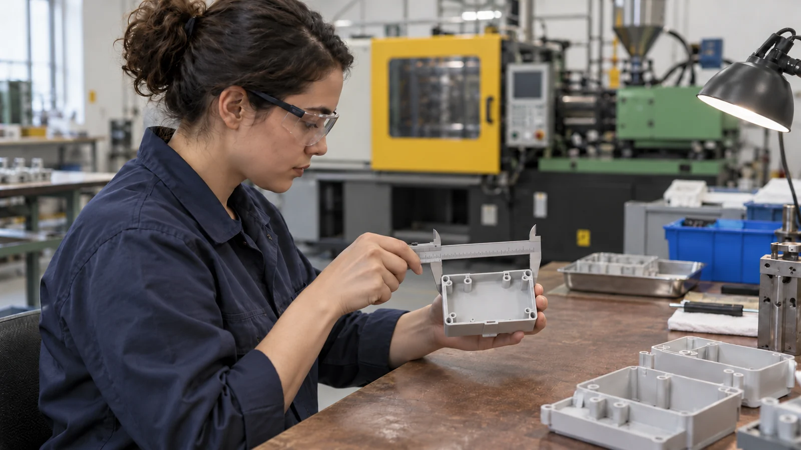
When the limiting issue is part or tool architecture, cycle-time work belongs in the broader custom mold design and tooling review, not solely in machine settings. A process adjustment cannot reliably compensate for a cooling circuit that misses a hot spot or an ejection layout that distorts the part.
What buyers should request in a cycle-time review
When comparing quotes or discussing an improvement, ask for the timing definition, resin and grade, part and wall-thickness assumptions, cavity count, quality acceptance criteria, and whether the figure comes from simulation, a mold trial, or sustained production. Ask which phase is expected to change and what inspection will prove that the faster cycle remains acceptable.
For a production program, compare cost per accepted part rather than cycle seconds alone. A faster cycle that increases rejects, rework, or downstream sorting can reduce usable output. The same principle applies when a mold design is updated: establish which dimensions and appearance features are critical, and confirm that the revised process continues to meet them.
Preguntas frecuentes
What is included in injection molding cycle time?
Usually the complete repeating sequence from one injection start to the next, including filling, packing/holding, cooling, and mold reset. Because some machine actions overlap, define the measurement points before comparing values.
Does cooling always determine the cycle?
No. Cooling is often a major part, but screw recovery, ejection, mold movement, manual handling, or a required hold phase can be the constraint on a particular job.
Can lowering mold temperature reduce cycle time?
It may change heat removal, but it is not a universal shortcut. A lower setting can affect surface quality, residual stress, weld lines, or dimensions. Validate the part and process after any change.
How should a supplier report a cycle-time target?
State the start/end definition, material grade, cavity count, quality criteria, and whether the number is simulated, trial-based, or a sustained average. Include good-part output so the comparison reflects accepted production.
Siguiente paso: Share the part model, resin specification, target volume, critical dimensions, and acceptance criteria so the cycle can be reviewed as a design-and-process system rather than a single timer.