
Large part injection molding warpage is often blamed on cooling, but the shape change can begin earlier—in the way the part fills, packs, releases, and is supported after ejection. On a large component, a small difference between regions can become visible as twist, bow, edge lift, or a mismatch at assembly. The first task is to identify where the deviation starts and whether the same pattern repeats.
Do not flatten the part by force and call it a process fix. Record the free-state shape, support condition, measurement orientation, and time after molding. A large part can sag under its own weight or change with handling, so inspection method is part of the diagnosis.
Describe the shape before naming the cause
Define the deformation in terms that another person can reproduce: which edge lifts, which datum shifts, whether the panel bows inward or outward, and whether the twist runs corner-to-corner. Photograph the part on a neutral surface and mark the measurement points. Compare the same locations across parts from different cavities or cycles where possible.
Separate a consistent shape bias from random variation. If every part bends in a similar direction, investigate a systematic geometry, tooling, or process influence. If the direction changes from part to part, review cycle consistency, material condition, ejection, and handling before redesigning the tool. Preserve samples from both acceptable and rejected parts.
Look for structural transitions and asymmetry

Long panels, offset ribs, thick bosses, large openings, and changes in wall section can create different stiffness and cooling behavior across one component. A broad surface may appear flat in the CAD model yet have little resistance to bending once it is free of the mold. Review the load path and the location of mounting points as well as the nominal wall thickness.
Compare both sides of the part for ribs, texture, material buildup, gate entry, and features that constrain shrinkage. The relevant issue is not simply whether the design is symmetric on screen; it is whether the tool and part experience balanced filling, packing, cooling, and release. A mold flow analysis may help frame questions about flow and cooling balance, but the actual tool and molded part determine whether a proposed change works.
Trace filling, packing, and cooling together
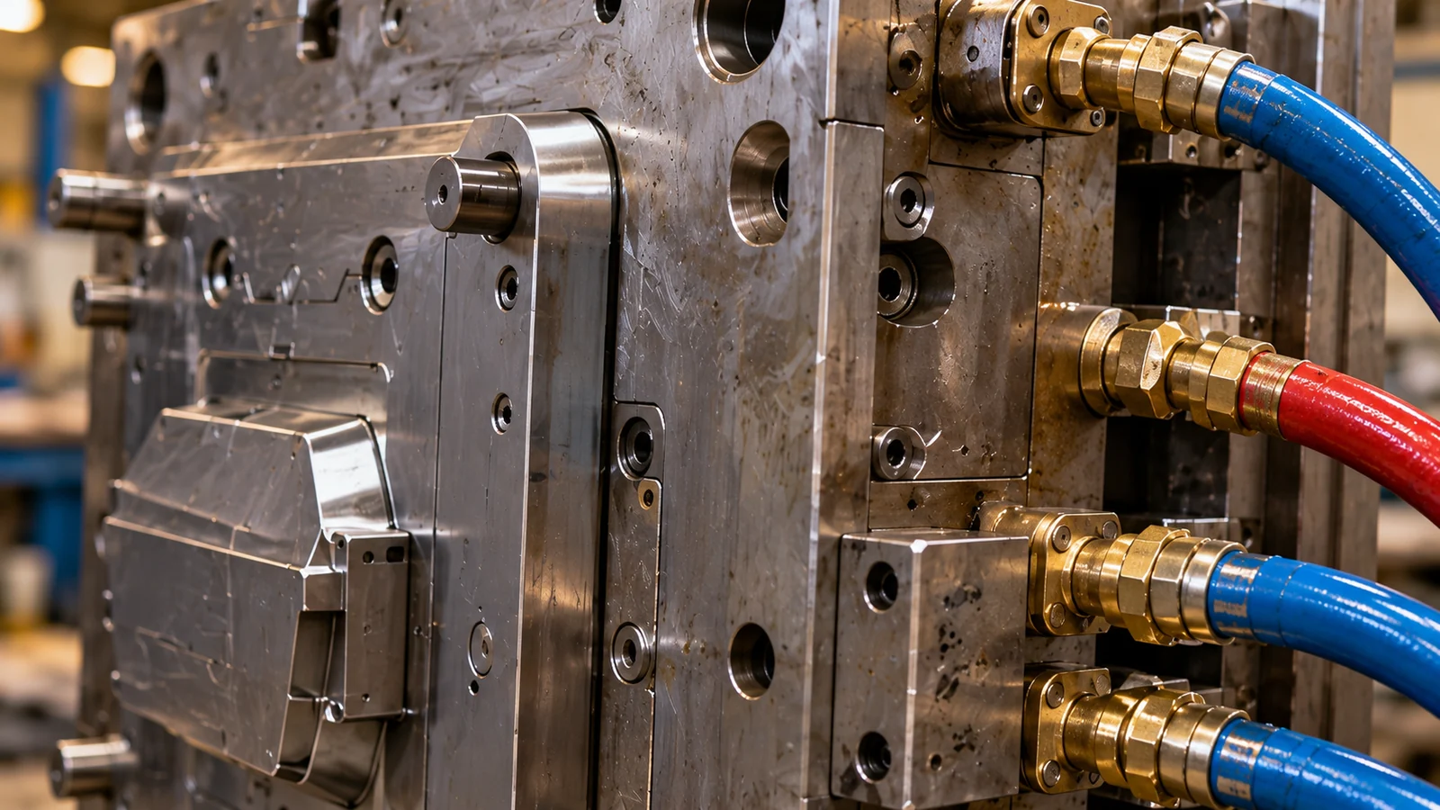
Use a controlled comparison rather than changing several settings at once. Connect each sample to the process record and note whether the deformation changes with cycle conditions, startup, material lot, or a tool adjustment. Check the gate and flow path, transfer behavior, packing consistency, local cooling, and ejection timing as a connected system.
- Confirm the baseline. Record the accepted process recipe, resin identification, cavity, and the way the part is removed and supported.
- Check regional differences. Compare cooling circuits, wall transitions, and the sequence in which regions fill and pack.
- Inspect release and handling. Look for drag marks, sticking, ejector witness, or distortion introduced while the part is warm.
- Test one hypothesis. Make one documented adjustment, then compare the same dimensions and free-state shape across repeated parts.
A process adjustment that improves one edge but worsens a mounting feature has not solved the problem. For a tool change, agree on the dimensional and functional checks before the next injection mold trial and validation.
Separate molding variation from measurement effects
Large components are sensitive to how they are held and measured. Confirm that the fixture does not pull the part flat, that the datum scheme matches assembly, and that all samples are measured in the same orientation and support condition. If the part changes after demolding, define when measurement occurs and keep that interval consistent.
Also distinguish a cosmetic bow from a functional failure. If the part assembles on defined datums and performs as required, a nonfunctional contour may not need the same tolerance as a sealing or alignment feature. Conversely, forcing a flexible part into a fixture can hide an assembly issue. State the acceptance condition clearly and validate the part in a representative assembly where appropriate.
When the design, tool, and measurement method all contribute, use a joined review rather than an isolated setting change. The overall plastic injection molding plan should align geometry, tool support, process controls, and inspection criteria.
FAQ
Does a warped large part always need more cooling time?
No. Cooling is one factor, but filling, packing, geometry, ejection, and handling can also contribute. Establish the deformation pattern and test one cause at a time.
Why does a large part look flat in the fixture but curve after removal?
The fixture may be constraining the part. Compare free-state and supported measurements, and confirm that the inspection condition reflects how the part is assembled and used.
Should the entire part have one flatness tolerance?
Not automatically. Identify which surfaces control fit or function, set datums around those interfaces, and define separate cosmetic or nonfunctional criteria where needed.