
LSR overmolding for robotic seals can create an integrated sealing feature when the rigid substrate, liquid silicone rubber grade, and seal geometry are designed as one interface. The word “overmolded” alone does not establish leak performance. Seal compression, mating-surface flatness, substrate movement, bond or mechanical retention, and assembly damage all affect the result. First define what must be kept out, where the joint moves, and how the finished assembly will be tested.
Define the seal’s job before selecting LSR
Start by describing the exposure and the consequence of ingress. Is the seal intended to exclude dust, splash, cleaning fluid, oil, or another specified medium? Does the joint remain static after assembly, or does it rotate or flex? Those conditions change how the seal is supported and how it should be tested.
Separate the sealing function from nearby features. A molded lip may seal against a cover, while a fastener carries clamp load and a locator controls position. If the cover can shift or bow, the seal may lose compression even when the LSR itself is intact. Document the mating geometry, closure sequence, and any permitted gap or movement before choosing the material or bead shape.
This is a component-level topic within robotics injection molding. The broader industry page helps locate the application; the sealing design still needs its own exposure, interface, and verification requirements.
Check substrate and adhesion assumptions
LSR does not bond to every rigid plastic or metal in the same way. Adhesion depends on the specific substrate grade, surface condition, LSR formulation, process, and any surface treatment or primer. If the seal relies on chemical bonding to stay in place, verify that exact material pair with the material supplier and a representative molded specimen.
Where bond strength is uncertain or not the primary retention method, consider mechanical capture. A groove, hole, wraparound edge, or other retaining geometry may keep the seal in position, but each feature affects tooling, fill, and demolding. Make sure a retention feature does not create a thin LSR section that tears during assembly or traps contamination at the interface.
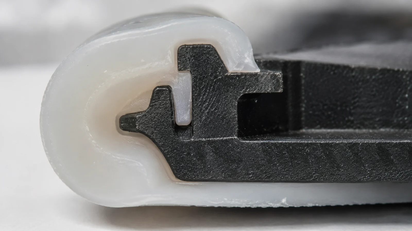
Review the current liquid silicone rubber molding process options with the rigid substrate and end-use conditions. Do not assume that one LSR grade, surface treatment, or bonding result applies to every enclosure.
Design compression and the mating surface
A seal needs a controlled squeeze against a defined mating surface. Too little compression can leave a leakage path; excessive compression can distort the cover, raise assembly force, or damage the seal over time. The acceptable range depends on the specific LSR grade, seal cross-section, groove geometry, assembly tolerances, and exposure, so obtain grade-specific design guidance rather than choosing a universal percentage.
Make the mating surface inspectable. A parting line, gate vestige, sink, flash, or scratch across the sealing path can become a leak channel. Keep the seal path away from unnecessary interruptions and establish the flatness or surface condition needed for function. If the robot joint needs service access, the seal also has to tolerate the planned disassembly and reassembly sequence.
Consider corner radii and transitions where the seal changes direction. Sharp turns, abrupt thickness changes, or narrow lips can complicate filling and increase damage during assembly. Use a design that supports the elastomer continuously and prevents it from rolling or being pinched when the cover closes.
Protect the seal through molding and assembly
LSR molding relies on a controlled cavity and material flow. Parting-line placement, venting, shutoff details, and gate location affect flash and the quality of the sealing edge. Flash on a nonfunctional edge may be a cosmetic issue; flash on the seal path can prevent the mating surfaces from closing as intended.
Plan how the rigid substrate is located and supported during the LSR shot. If it shifts, the seal can become uneven in height or position. The assembly fixture should also prevent a sharp edge or fastener from cutting the elastomer during closure. Protect the molded seal during handling and packaging so the first inspection is not followed by damage before assembly.
Define visual criteria for the seal path and dimensional criteria for the features that control compression. Inspection should distinguish harmless appearance variation from a void, tear, short fill, or flash condition that crosses the functional path.
Validate the assembled joint
Material data and a coupon bond test are useful inputs, but the final decision belongs to the assembled joint. Test the intended cover, fasteners, compression, cable entries, and movement. Select a leak or ingress test that matches the actual exposure and acceptance requirement; do not infer a protection rating from the presence of an LSR bead.
- Confirm the interface: inspect seal continuity, position, flash, and mating-surface condition.
- Measure closure: verify the assembled gap or compression at the critical locations.
- Test the relevant exposure: use the specified dust, liquid, cleaner, or temperature condition.
- Cycle the joint: include motion, vibration, thermal change, or service cycles if relevant.
- Inspect after test: look for compression set, rolling, tearing, bond separation, and ingress evidence.
If the seal passes before movement but fails afterward, inspect joint deflection and fastener retention as well as the LSR. If it passes a static exposure but fails after service, check assembly handling and seal recovery after disassembly.
| Failure evidence | Possible interface cause | Next check |
|---|---|---|
| Leak along one edge | Uneven compression, cover bow, or local surface defect | Map assembled gap and inspect the sealing land |
| Seal displaced after assembly | Insufficient capture or assembly drag | Review groove, retaining geometry, and closure path |
| Separation at substrate | Unverified material pair or surface condition | Confirm grade compatibility and test representative parts |
FAQ
Does LSR overmolding automatically make a robot joint waterproof?
No. An LSR feature does not by itself establish an ingress rating. The assembled joint, mating surfaces, compression, cable entries, and specified test must all be evaluated.
Does LSR bond to every engineering plastic?
No. Bonding depends on the exact grades, surface condition, and process. Confirm the material pair with supplier data and representative molded-part testing.
What information is needed to review an LSR seal?
Provide the rigid substrate grade, assembly CAD, seal path, mating surface, exposure, movement, disassembly needs, and the acceptance test or leakage limit the product must meet.