
High-voltage battery module architectures require exceptional safety, robust electrical isolation, and flawless fire containment.
Designing these composite assemblies involves placing individual lithium-ion cells inside highly structured, thin-walled plastic carriers.
These structural cell carriers protect the battery cells from mechanical vibration and road shocks during daily driving.
Transitioning custom packaging designs from low-volume quick-turn checks into continuous high-volume production is the ultimate scaling challenge.
Selecting certified, fully traceable engineering materials ensures that your battery pack components conform to international safety regulations without sacrificing structural performance.
This technical guide explores the vertical flammability test standards, raw material traceability protocols, and advanced molding methods necessary to produce high-yield, crack-free components.
Table of Contents
- 1. Understanding UL94 V-0 Flammability Tests for Powertrains
- 2. Sourcing Certified Resins with UL Yellow Card Traceability
- 3. Tooling Optimization to Prevent Notch Sensitivity and Stress Cracking
- 4. Controlling Warpage and Tight Tolerances in Grid-Like Matrices
- 5. Post-Mold Annealing Processes for Thermal Stress Relaxation
Understanding UL94 V-0 Flammability Tests for Powertrains
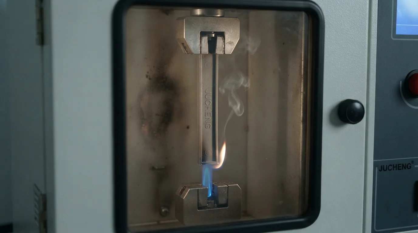
Establishing high-quality UL94 V-0 flame retardant plastic cell carrier injection molding requires strict compliance with vertical flammability parameters.
During standard vertical burn testing, technicians suspend a standardized plastic specimen vertically above a calibrated methane burner to measure afterflame and afterglow times.
To satisfy a V-0 rating, the polymer must self-extinguish within 10 seconds of flame removal, and absolutely zero flaming drips may ignite the surgical cotton placed below the testing fixture.
E-mobility safety regulations demand V-0 compliance because vertical fire propagation inside a packed battery module leads to catastrophic thermal runaway.
Lower flammability ratings like V-1 or V-2 allow longer afterflame times or permit flaming drops to ignite the cotton, which is unacceptable for high-voltage cells.
Sourcing Certified Resins with UL Yellow Card Traceability
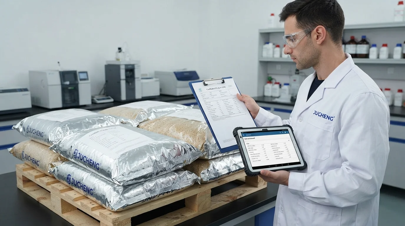
Incoming raw material quality dictates the fire safety performance of the molded carriers.
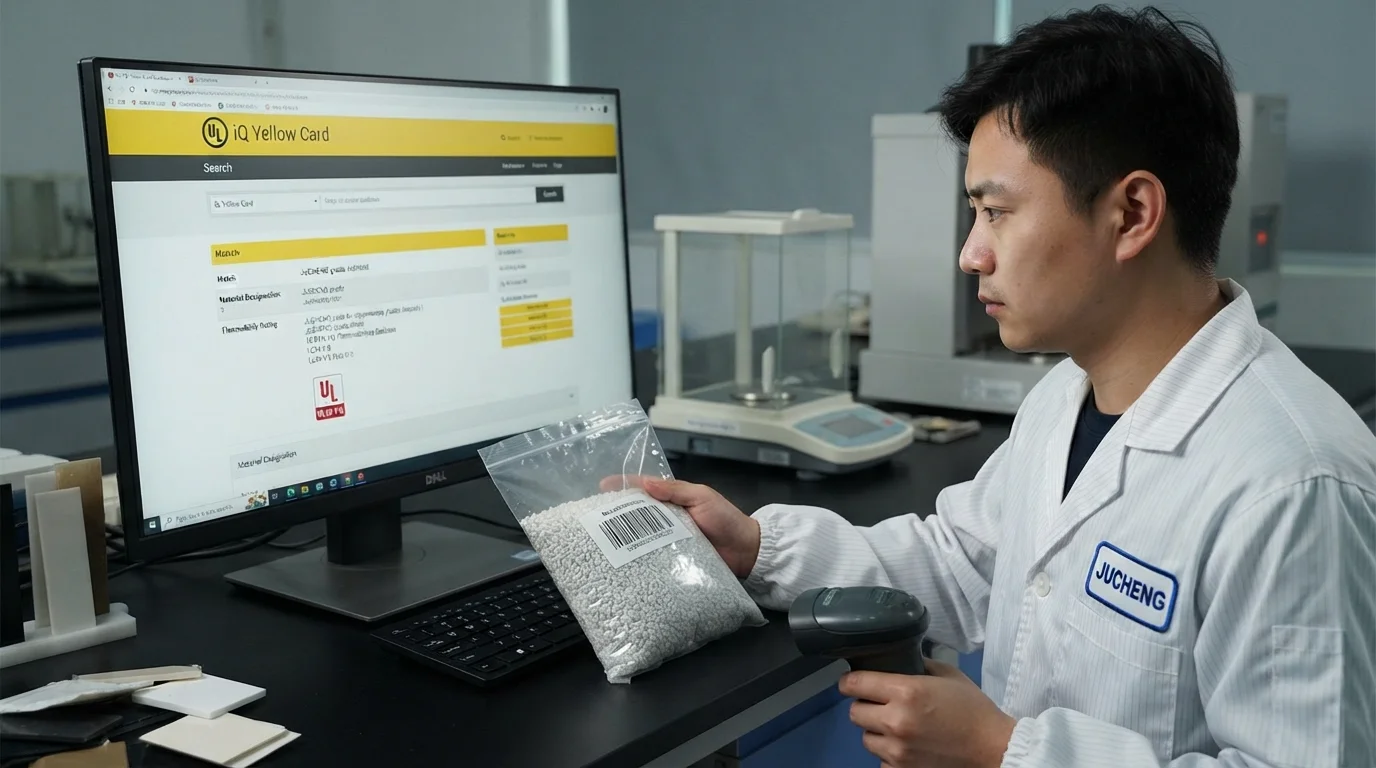
JUCHENG Injection Molding utilizes the UL Yellow Card database to verify the specific gravity, flammability rating, and heat deflection temperature of every resin batch.
Sourcing only from certified material suppliers prevents trace contaminants from entering the molding hopper.
Contamination, even at minute levels of 0.05%, can degrade the polymer structure during processing, compromising flammability performance.
Establishing raw material yellow card verification ensures that every production batch conforms to the exact material specifications.
This rigorous document control prevents the use of uncertified materials, protecting automotive tier-1 brands from regulatory non-compliance.
Tooling Optimization to Prevent Notch Sensitivity and Stress Cracking
Processing highly complex cell carriers presents severe manufacturing difficulties because flame-retardant additives act as physical impurities inside the base polymer matrix.
Flame-retardant (FR) formulations, typically based on polycarbonate blends (PC/ABS), polybutylene terephthalate (PBT), or polyamide (PA66), contain organic phosphorus compounds that disperse throughout the carbon backbone.
High shear rates during injection molding force these additive molecules to migrate out of the polymer suspension.
This migration creates localized high-concentration zones near injection gates or sharp geometric transitions.
Consequently, the material suffers from localized notch sensitivity and high molded-in residual stresses.
Exposing these high-stress zones to mechanical road vibration or battery electrolyte vapors triggers rapid environmental stress cracking (ESC).
To neutralize stress concentration, mold designers utilize larger gate cross-sections, preferring fan or tab gates over restrictive pin gates.
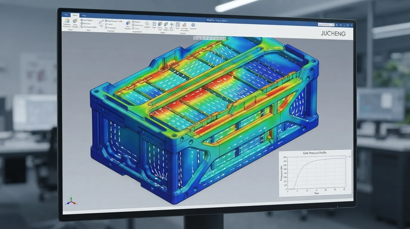
Fan gates distribute melt pressure evenly across the filling path, preventing frictional shear degradation of the organic FR agents.
Furthermore, using generous radii on all internal corners—ideally 50% to 60% of the nominal wall thickness—prevents physical stress-riser points from shearing the surrounding plastic.
Our tooling group utilizes advanced finite element mold flow analysis to predict shear stress hotspots before cutting metal.
Adjusting injection speed profiles dynamically during cavity filling ensures that shear rates remain within safe limits.
These processing safeguards maintain the original molecular weight of the polymer, ensuring the carrier survives standard automotive durability trials.
Controlling Warpage and Tight Tolerances in Grid-Like Matrices
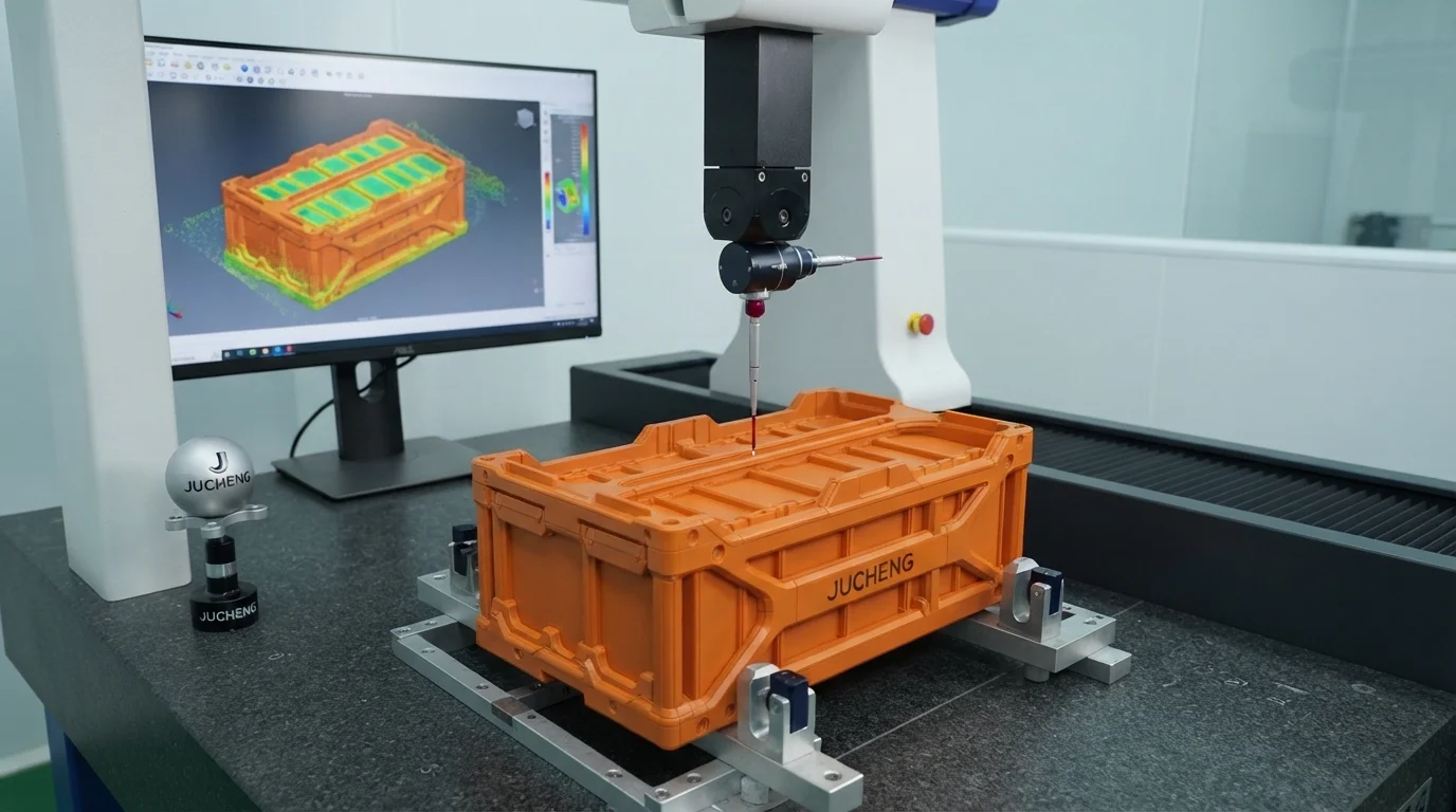
Mitigating warpage during UL94 V-0 flame retardant plastic cell carrier injection molding is highly challenging because of complex part geometry.
Cell carriers are grid-like structures featuring thin walls (often 1.2mm to 1.5mm) and hundreds of cell pockets, where differential cooling rates trigger anisotropic shrinkage.
Amorphous resins contract uniformly, but adding glass fibers or flame-retardant packets introduces shrinkage differentials along and across the polymer flow fronts.
Even a minor twist of 0.1mm prevents automated robotic arms from inserting battery cells during pack assembly, resulting in rejected batches.
To achieve a tight pocket concentricity and overall carrier flatness, tooling designers integrate precise water cooling circuits across every cell pocket core pin.
This dynamic cooling balance ensures uniform cooling rates across the matrix, preventing anisotropic shrinkage stresses from warping the grid.
We also optimize clamping pressure profiles on our 35+ injection machines to prevent overpacking of the cavities near the runner drop-points.
Proper packing control ensures consistent density throughout the thin-walled ribs, eliminating dimensional twist.
Post-Mold Annealing Processes for Thermal Stress Relaxation
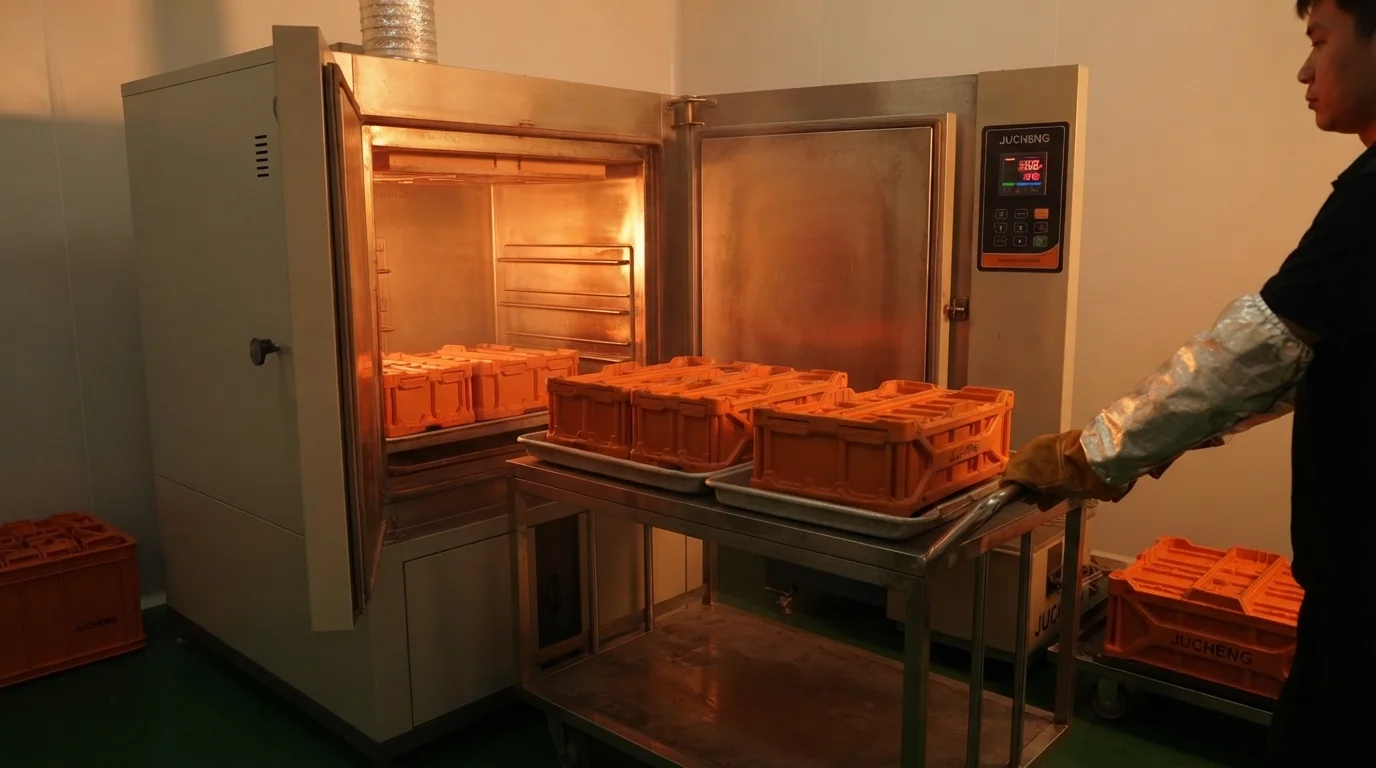
Baking the finished carriers in specialized industrial ovens relieves residual stresses that develop during cooling.
Annealing at temperatures of 110°C to 120°C for approximately 2 hours relaxes the high-tension polymer molecules.
This thermal post-treatment prevents environmental stress cracking from developing after long service hours in high-temperature environments.
Successful implementation of UL94 V-0 flame retardant plastic cell carrier injection molding provides the internal structural base required inside custom plastic battery housings for EV.
By combining precision tooling with IATF 16949-certified quality systems, JUCHENG offers reliable manufacturing solutions.
Frequently Asked Questions (FAQ)

Why do flame-retardant polymers exhibit higher stress cracking than standard grades?
Flame-retardant additives act as physical impurities that migrate under high shear rates, forming high-concentration zones at weld lines or sharp corners. This migration creates notch sensitivity and traps molecular stresses that crack easily under vibration.
How do you verify the flame-retardant rating of a molded carrier batch?
Quality verification incorporates incoming raw material inspection and post-mold vertical burn testing. Our quality control team checks the Certificate of Analysis and cross-references the batch number with the official UL Yellow Card database.
What is the impact of regrind material on UL94 V-0 compliance?
Using regrind material can significantly compromise flame retardancy. Reprocessing subjects the polymer and FR additives to multiple thermal cycles, triggering thermal degradation and reducing the flammability rating from V-0 to V-2.