
Injection molding flash is easy to spot and surprisingly easy to misdiagnose. A thin fin at the parting line may come from a mold that no longer closes uniformly, but flash can also appear at an insert, slide, ejector pin or vent. Raising clamp force or lowering injection pressure may hide the symptom while creating a different defect. The useful first question is not “Which setting should we change?” but “Where does the flash begin, and what changed when it appeared?”
A location-first diagnosis turns a cosmetic symptom into a traceable mold and process problem. It also helps buyers separate a temporary process correction from work that belongs in maintenance or part design.
Quick diagnostic: record the exact location, whether flash is continuous or local, the cavity or mold area affected, and whether it appeared after a tooling, material, setup or production change. Then change one variable at a time.
Neste artigo
- Map the flash before changing settings
- Separate closure problems from process problems
- Run a controlled correction
- When geometry or venting is the constraint
- When trimming helps—and when it does not
- What to include in a supplier handoff
- Perguntas frequentes
Map the flash before changing settings

Mark the defect on a drawing or photo and compare several consecutive parts. A continuous fin around the parting line calls for a different investigation than a short segment at one insert or a repeated mark beside an ejector pin. Check whether it occurs in every cavity, one cavity, or only after the mold reaches operating temperature.
| Flash location | Evidência a verificar | Do not assume |
|---|---|---|
| Broad parting-line fin | Seating, alignment, clamp condition, surface damage | More clamp force is always the fix |
| One insert or shutoff | Local wear, debris, fit, support, thermal movement | The whole mold is misaligned |
| Vent or ejector feature | Vent condition, local pressure, pin clearance | All flash is poor venting |
Note the resin lot, machine, cavity, cycle count and process state. If flash begins after a maintenance event or long run, that timeline may be more useful than one pressure reading. A sound injection mold design review considers shutoffs, parting surfaces, vent locations and tool support—not just nominal geometry.
Separate closure problems from process problems
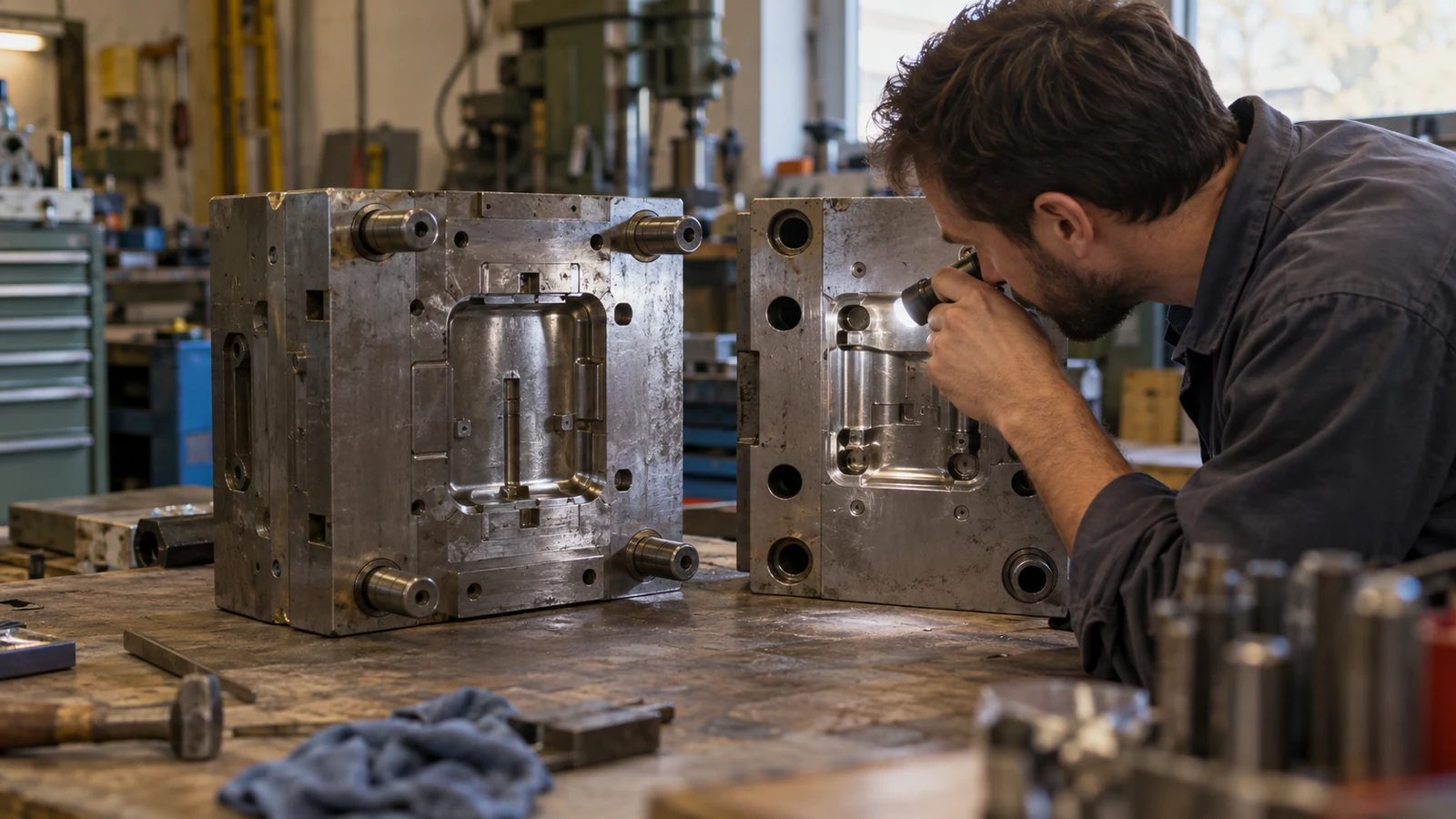
Flash forms when melt enters a gap that should remain closed or when a vent or clearance passes more material than intended. The gap may come from wear, a damaged shutoff, contamination, uneven seating or deflection under load. Process conditions may increase cavity pressure, but they do not make every gap a process-only issue.
Inspect the suspect area safely. Look for residue, trapped debris, impact marks and uneven contact. If one cavity flashes while the others do not, investigate local tool or flow differences before changing the full process. If all cavities develop broad flash together, review shared closure conditions and the documented process window.
Do not infer clamp tonnage from the part alone. Confirm the machine and mold setup, projected area and any cavity-pressure evidence available. Excessive clamp force can increase tool stress; lowering speed or pressure indiscriminately can create short shots or weak weld areas.
Run a controlled correction
Once tool condition is understood, run a documented trial instead of simultaneous adjustments. Keep resin, drying practice, mold temperature, cycle stage and measurement method consistent. Change one relevant variable, record the result by cavity, and retain a sample from each step.
- Set the baseline. Record location, dimensions, cavity, machine settings and part weight.
- Inspect the tool. Clean and check closure surfaces and vents before compensating with process changes.
- Adjust inside the validated window. Test a measured change only when evidence points to a process cause; check fill, dimensions and appearance together.
- Recheck after stabilization. Compare parts after the mold reaches its normal thermal state.
A useful correction removes flash without moving the part outside functional requirements. If it creates incomplete fill, sink, distortion or unstable cycling, it has shifted the problem rather than solved it.
When geometry or venting is the constraint
Thin shutoff lands, long flow paths, abrupt thickness transitions and local pressure peaks can reduce tolerance to normal variation. A vent that is too shallow may trap gas; one that is too deep or poorly supported may become a flash path. “Add venting” is not universal advice.
Review resin, gate position, wall transitions and mold construction together. A filling study can help locate pressure buildup, while a tool review determines whether a proposed vent or shutoff is practical to machine and maintain. The broader moldagem por injeção de plástico should be judged against part acceptance criteria, not a cosmetic target alone.
Where the drawing permits an edge condition, define a maximum by location and function. A seal, sliding interface or visible edge may need a stricter limit than a hidden nonfunctional edge.
When trimming helps—and when it does not
Secondary deflashing can work when the specification allows a removable edge and the feature is consistently accessible. It is not a substitute for a damaged shutoff or flash that changes fit, sealing or assembly. Trimming may leave a witness or inconsistent edge in hard-to-reach areas.
Before approving it, define the area, removal method, edge limit and inspection method. Compare handling, labor and quality risk with a tool correction. If flash returns unpredictably, address the source first.
What to include in a supplier handoff
Provide the part number and revision, resin grade, mold and machine ID, cavity, defect photos with a scale, when the defect begins, recent changes and the functional limit. State whether the concern is appearance, assembly, sealing or safety. This evidence helps the engineering team distinguish a local shutoff issue from a process-window issue.
Perguntas frequentes
Should clamp force be increased to stop flash?
Only if evidence shows mold separation under cavity pressure and the setup remains within approved limits. Inspect alignment and closure surfaces first; extra force can mask damage and add stress.
Can lower injection pressure always eliminate flash?
No. It may reduce melt entering a gap but can cause short shots or poor feature replication. Diagnose first, then make one controlled change while checking part function.
Is flash acceptable if it can be removed?
That depends on the drawing and part function. Removal may be unacceptable on sealing, mating or safety-related surfaces. Agree on an edge limit and secondary operation before release.