
엄격한 치수도 광학적으로는 실패할 수 있습니다. 광학 사출 성형 공차는 개별 수치가 아니라 관계를 제어해야 하기 때문입니다. 렌즈는 직경, 두께 및 평탄도 한계를 충족하면서도 광축이 장착 기준면에서 벗어날 수 있습니다. 투명 창은 프로파일 검사를 통과하고도 국부적 형상 오차나 성형 응력으로 인해 이미지를 왜곡시킬 수 있습니다.
더 나은 출발점: 광학적 출력과 그 기계적 기준을 정의하고, 어떤 변동이 그 출력을 변화시키는지 식별한 다음, 그러한 기여 요소에 공차와 검사 방법을 할당하십시오.
이 글에서:
광학적 실패를 측정 가능한 기여 요소로 전환하십시오
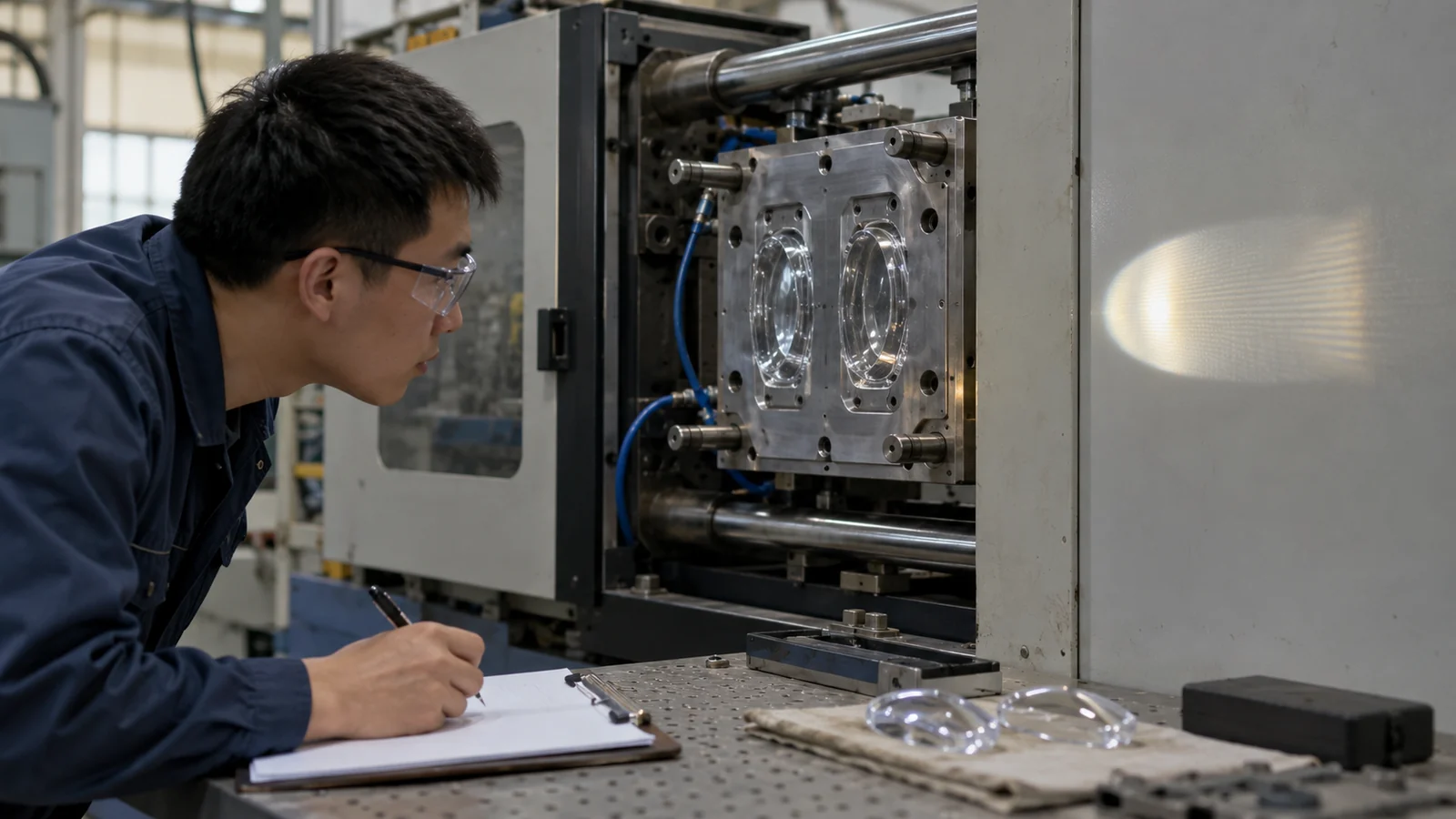
결상 광학계의 경우, 허용할 수 없는 결과는 흐림, 왜곡 또는 초점 이동일 수 있습니다. 도광판의 경우, 휘도 불균일 또는 크로스토크일 수 있습니다. 보호 창의 경우, 투과 파면 오차 또는 가시적 왜곡일 수 있습니다. 각 결과는 기하학, 재료 및 응력의 서로 다른 조합에 반응합니다.
가능한 경우 민감도 분석을 사용하십시오: 광학 모델에서 하나의 기여 요소를 변화시키고 출력을 관찰하십시오. 이는 중심 두께, 곡률, 편심, 기울기 또는 표면 형상 중 어느 것이 가장 엄격한 제어를 받아야 하는지 밝혀줍니다. 또한 기능적 영향이 거의 없는 치수에 비용이 지출되는 것을 방지합니다.
기준면 체계는 조립을 견뎌야 합니다
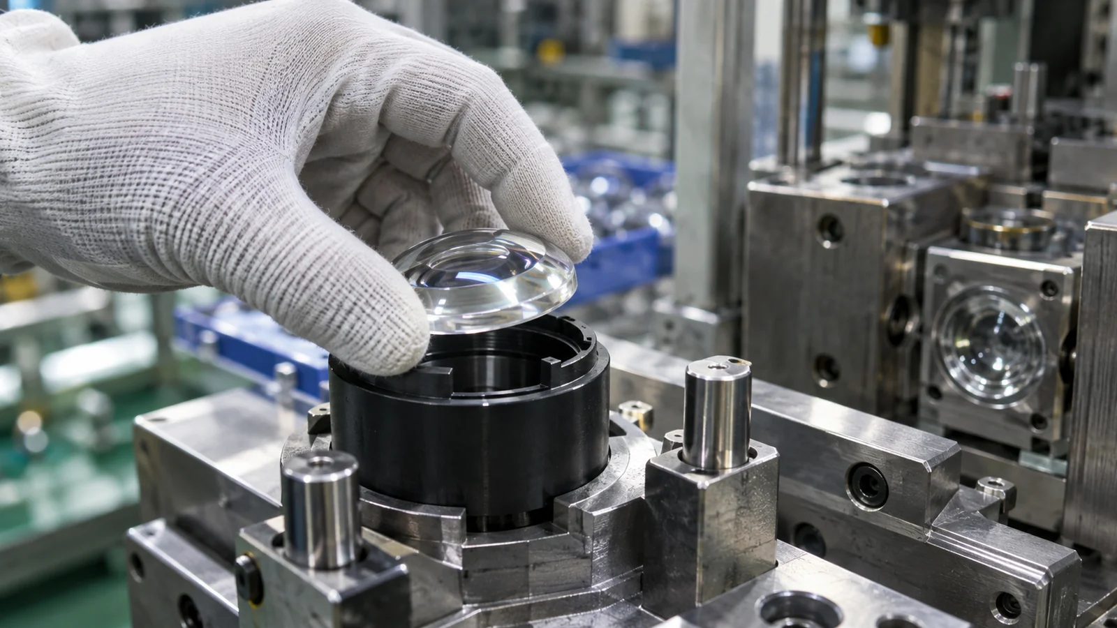
제품에서 부품이 어떻게 위치되는지를 나타내는 기준면을 선택하십시오. 검사에서 렌즈를 광학 표면에 중심을 맞추지만 조립에서는 세 개의 플라스틱 패드로 위치를 잡는다면, 두 조건이 일치하지 않을 수 있습니다. 광축 또는 개구부를 실제 장착 특징부와 연관시키십시오.
측정 중 유연한 부품을 과도하게 구속하지 마십시오. 휘어진 창을 강제로 평평하게 만드는 고정구는 자유 상태에서는 존재하지 않는 허용 가능한 프로파일을 보고할 수 있습니다. 반대로, 조립체가 의도적으로 부품을 구속할 수도 있습니다. 이 경우에는 제어된 조건을 정의하고 이를 일관되게 재현해야 합니다.
금형, 공정 및 조립 전반에 걸친 오차 예산
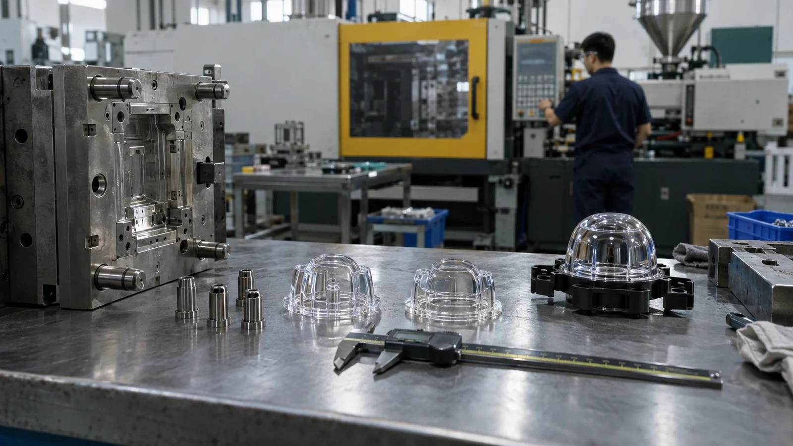
최종 광학 정렬에는 캐비티 형상, 인서트 위치, 성형 수축, 이젝션 변화, 컨디셔닝, 하우징 변동 및 조립 하중이 포함됩니다. 허용 가능한 전체 오차를 성형 부품에 할당하는 것은 나머지 누적 오차를 무시하는 것입니다. 성형에 비현실적으로 작은 비중을 할당하면 제품 개선 없이 검사 분쟁만 초래할 수 있습니다.
| 기여 요소 | 일반적인 질문 | 제어 경로 |
|---|---|---|
| 광학 인서트 | 형상 또는 위치가 변하는가? | 인서트 계측 및 캐비티 추적성 |
| 성형 공정 | 수축이 안정적으로 유지되는가? | 창 연구 및 부품 능력 |
| 조립 | 고정이 광학 부품을 기울이거나 응력을 가하는가? | 조립 게이지 및 기능 시험 |
하나의 계측기로 모든 요구사항을 입증할 수는 없다
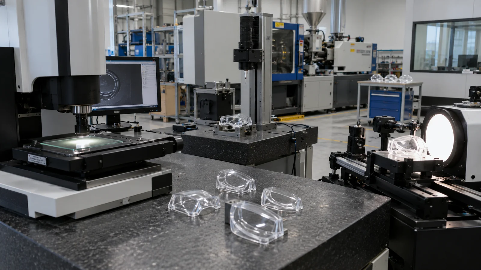
접촉식 게이지는 외경에는 적합할 수 있지만 광학 면을 손상시키거나 변형시킬 수 있습니다. 비전 시스템은 모서리와 데이텀을 측정할 수 있지만 3차원 표면 형상을 포착하지 못할 수 있습니다. 중요한 표면에는 간섭계, 프로파일로메트리 또는 기타 광학 계측이 필요할 수 있으며, 기능 벤치가 최종 빔 또는 이미지를 검증합니다.
Define fixture, orientation, temperature, conditioning time, filter settings and data reduction. Without a common method, two laboratories can report different values for the same part. Measurement-system analysis should precede arguments about small process differences.
Capability Data Must Stay Cavity-Specific

A combined capability number can hide one poor cavity behind several good ones. Track cavities separately during tool qualification and after maintenance. Also review trends over time; a centered short trial does not prove long-run stability.
In 광학 및 투명 사출 성형, dimensional capability should be connected to optical output. If a dimension remains capable while functional performance drifts, the control plan is missing a contributor such as stress, surface condition or assembly load.
Do not confuse resolution with measurement confidence
An instrument displaying additional decimal places is not automatically capable of accepting a tight tolerance. Fixture repeatability, edge detection, temperature, operator setup and data filtering all contribute uncertainty. Run repeatability and reproducibility work on representative transparent parts, because clear edges can behave differently from calibration artifacts.
Freeze the acceptance method with the drawing
State whether surface form is evaluated over the full aperture or after removing tilt and power, whether the part is free or constrained, and how outliers are treated. If buyer and supplier use different filters or fixtures, both can follow the drawing and still disagree. A shared method and correlated samples should be approved before production tooling is released.
Review tolerance changes as system changes
Tightening one molded dimension can shift cost into tool correction, cycle time, inspection and yield without improving the assembly. Before revising a limit, rerun the optical sensitivity and stack analysis. Sometimes a locating feature, compliant mount or calibration step controls output more effectively than a tighter lens dimension.
For procurement, request the proposed measurement method and capability by cavity rather than a generic promise of “high precision.” Ask which dimensions are controlled in the mold, which require process compensation, and which optical characteristics are verified functionally. This creates comparable quotations and exposes assumptions early.
자주 묻는 질문
Can standard molded-part tolerances be used for lenses?
They can guide nonoptical features, but optical surfaces and axis relationships need function-specific limits and measurement methods.
Should the CAD nominal equal the tool surface?
Not necessarily. Predictable molding shrinkage and form change may require compensated steel after stable trial data is available.
How should suppliers quote a tight optical tolerance?
They need the drawing, optical function, material grade, measurement definition, sample plan, assembly condition and acceptance data—not the tolerance value alone.