
A cavity may produce one acceptable trial part while cold cores or worn gates make repeat production unstable. The design review must cover thermal behavior and maintenance as well as the nominal shape. A reliable high temperature injection mold design must manage heat as deliberately as it manages shape. PEEK, PPS and PEI can require elevated melt and mold conditions, abrasive fillers and tight dimensional control. If heating, insulation, steel selection, venting and thermal expansion are treated as afterthoughts, process settings cannot rescue the tool.
Design review sequence:
- Define the resin and thermal window
- Map heat flow through the tool
- Select steel and components
- Place gates and vents
- Plan measurement and maintenance
The mold begins with the exact grade
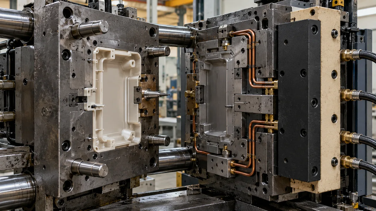
“PEEK mold” or “PPS mold” is not enough. Unfilled, glass-filled and carbon-filled grades change abrasion, shrinkage, flow orientation and surface expectations. Obtain the exact supplier grade, production volume, regulatory requirements and part acceptance criteria before the steel specification is frozen. Melt range, filler content, shrinkage and corrosive or abrasive behavior vary by grade. Cutting steel from a family-level assumption can place gates, vents and dimensions outside the usable window. Freeze the material designation or define a tested grade range before final design. The first design review should include the precise resin designation, filler type, critical dimensions, function and intended volume. If material alternatives remain open, identify the range of behavior the tool must accommodate rather than assuming one shrinkage value. Keep supplier recommendations and component requirements distinct. A temperature capability quoted for the molding machine does not establish that the completed tool, runner and auxiliary systems can safely maintain the required conditions at every critical surface.
Design a thermal circuit, not just drilled holes
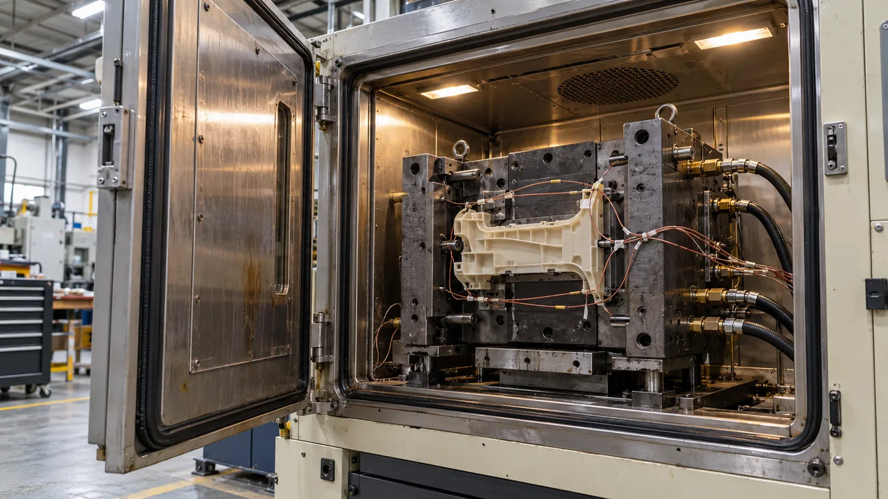
The objective is a controlled cavity and core surface, not a high temperature at the heater outlet. Circuit length, diameter, flow, insert contact, hose loss and heat transfer into platens all influence local conditions. Uneven temperature produces differential shrinkage, unstable crystallinity and changing dimensions through the shift. Deep cores, slides and thick inserts create local heat sinks that a uniform channel layout may not control. Thermal imbalance changes fill, crystallinity and ejection from cavity to cavity. Review circuit spacing with a thermal study and confirm surface temperatures after build. Cooling and heating provisions should be designed around local heat flow, including cores, slides, runners and thick sections.
Place measurement points where the part is sensitive: long flow ends, thick-to-thin transitions, critical datums and regions around large inserts. Unequal thermal paths can change fill and morphology between cavities even when the average display is stable. Plan measurement locations while the design is accessible, then compare predictions with surface measurements at trial. The acceptance check should include warm-up and restart as well as steady production, because local thermal lag can create failures that a single stabilized shot never reveals.
Keep tool heat out of the machine
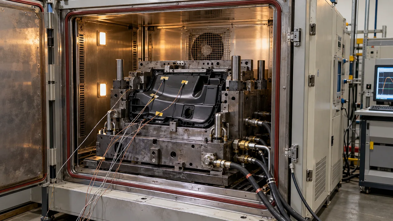
Thermal insulation between mold and platen reduces heat loss and protects the press. Hot hoses, manifolds, seals, sensors and connectors must be rated for the intended environment. Expansion allowances and support should prevent the heated assembly from losing alignment. Insulation limits heat loss into platens and neighboring mechanisms while reducing warm-up time. It must still support clamp load and avoid trapping heat around seals or electronics. Document allowable machine-interface temperatures during acceptance. Thermal isolation also affects fastening, alignment and load transfer, so it cannot be treated as a sheet added at the end of the design. Review nozzle contact, mounting interfaces, seals and nearby sensors against their actual ratings. Consider operator access and service procedures around hot components. The design record should state the required interface conditions and how they will be measured. That helps separate process instability caused by heat loss from equipment limits that require a different production arrangement.
Steel selection follows wear and life
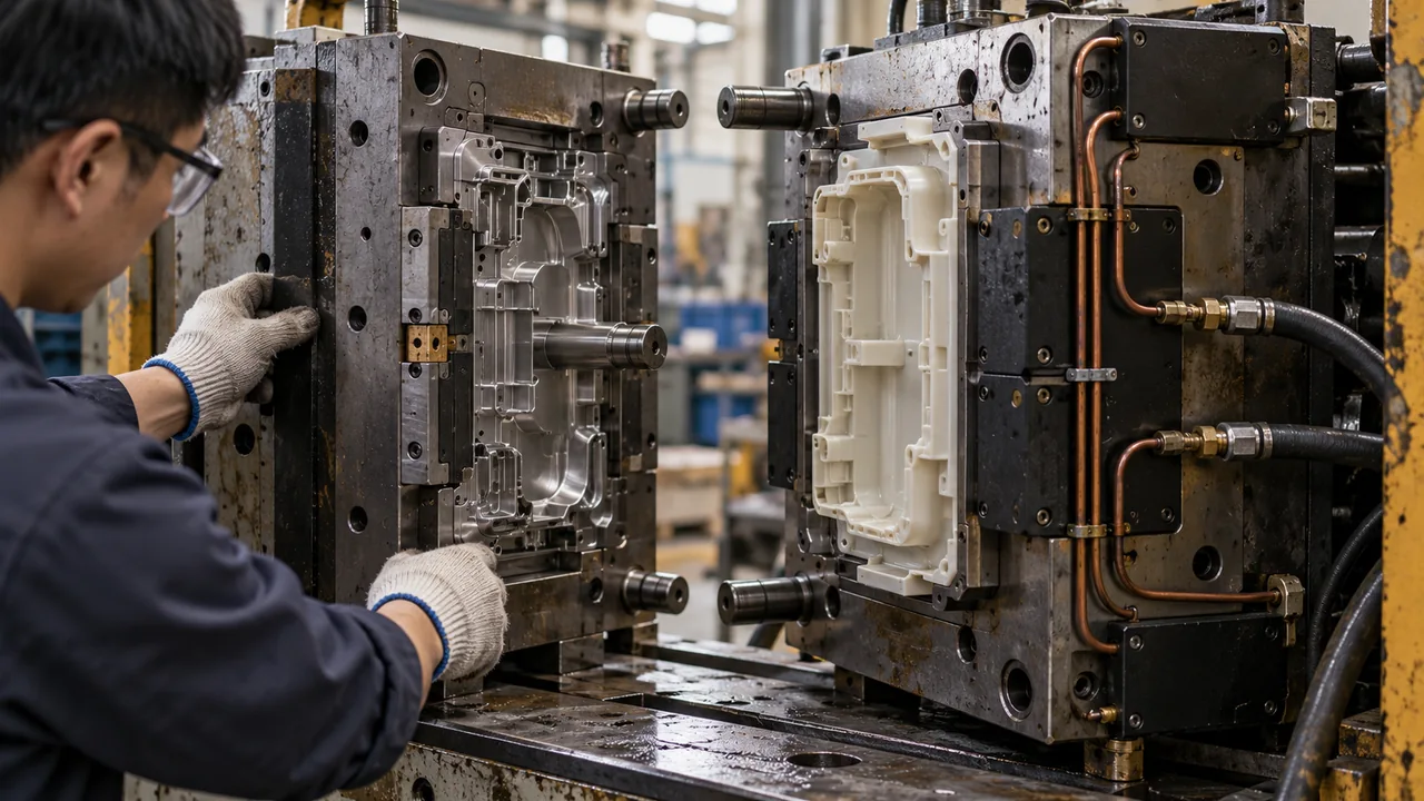
High temperature alone does not dictate one tool steel. Abrasive glass or carbon fiber, corrosion risk, polish requirement, cavity life and maintenance capability all matter. Hardened inserts may be appropriate at gates, shutoffs and high-velocity regions even when the full mold uses a different construction. Filled high-temperature polymers can erode gates, runners, vents and shutoffs in the highest-velocity regions. Uniformly premium steel is not always necessary, but vulnerable inserts must be serviceable. Plan hardness, coatings and replaceable details around predicted wear. Wear tends to concentrate where filled melt changes direction, accelerates or crosses a narrow opening. Gates, vents, runner bends and shutoffs may therefore need different protection or replacement plans from the rest of the cavity. Match steel, heat treatment and any coating to the grade and duty, using verified material compatibility. Include accessible replaceable inserts where justified. A durable mold is one whose critical geometry can be monitored and restored, not simply one described as using premium steel.
| Tool area | Design risk | 검토 질문 |
|---|---|---|
| 게이트 및 러너 | Shear, wear and freeze-off | Can the gate fill without excessive pressure or degradation? |
| 파팅 라인 | Flash and thermal movement | Will support remain uniform at operating temperature? |
| Vents | Burning and deposits | Are vents accessible for maintenance? |
Gate by load path as well as fill
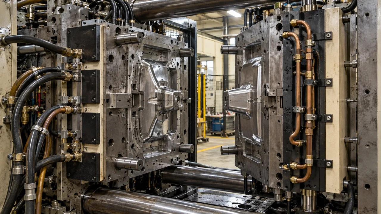
Gate location controls weld lines, fiber orientation and packing. For reinforced high-temperature polymers, these effects can dominate strength and warpage. Keep critical weld lines away from fasteners, pressure boundaries and highly loaded sections where possible. Gate position controls flow length, fiber orientation, air traps and the location where fronts meet. A cosmetically hidden weld line can still cross the highest mechanical load. Use simulation and short-shot evidence to confirm the design intent. A gate must provide filling and packing without placing weld lines, orientation or vestige at a function-critical feature.
A 몰드 플로우 해석 is valuable before steel when flow length is high, the part has multiple gates or orientation affects the structural design. A change that improves appearance can still weaken a seal land or loaded boss. Use the expected flow path to identify air traps and pressure loss, then confirm with representative short shots during trial. Filled grades require attention to load direction as well as shrinkage. Review the whole component before treating a larger gate or higher speed as a universal improvement.
Maintenance must be designed in
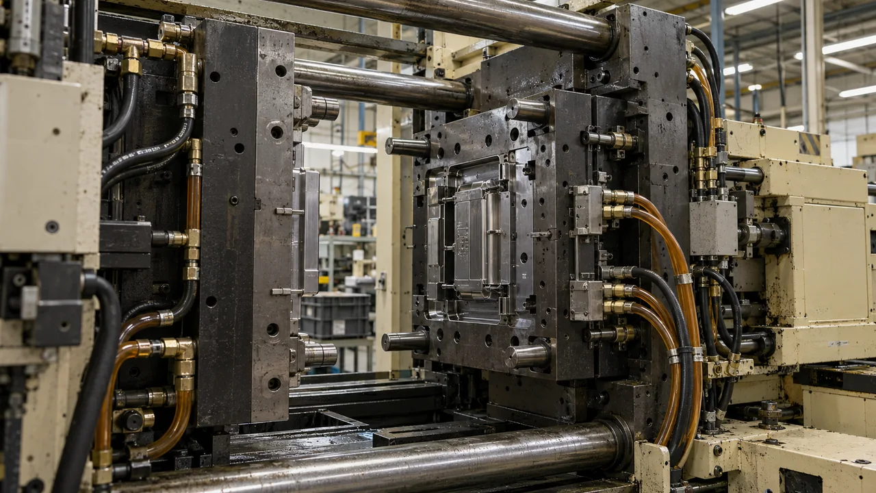
Provide access to vents, heaters, thermocouples and wear inserts. Record baseline resistance, flow and cavity temperature during qualification so maintenance can detect drift. A production tool that requires complete disassembly for routine vent cleaning will not remain stable for long. Hot molds and abrasive resins increase the cost of blocked vents, worn gates and damaged shutoffs. Accessible inserts and documented baseline dimensions shorten recovery. Define inspection intervals from shot count and observed wear rather than waiting for rejects. Define baseline gate, vent and shutoff dimensions after acceptance, and retain cavity-specific inspection results.
Jucheng의 고온 폴리머 성형 approach connects mold design with the exact PEEK 또는 PPS grade and the validation plan. Schedule maintenance from observed wear and production history rather than using an invented lifetime guarantee. Tool servicing should preserve the heating layout and sensor locations needed for repeatability. After a repair, confirm both dimensions and function under the approved process. This prevents a locally successful polish or insert change from altering flow, packing or release in another critical region.
자주 묻는 질문
Can water circuits heat a high-temperature mold?
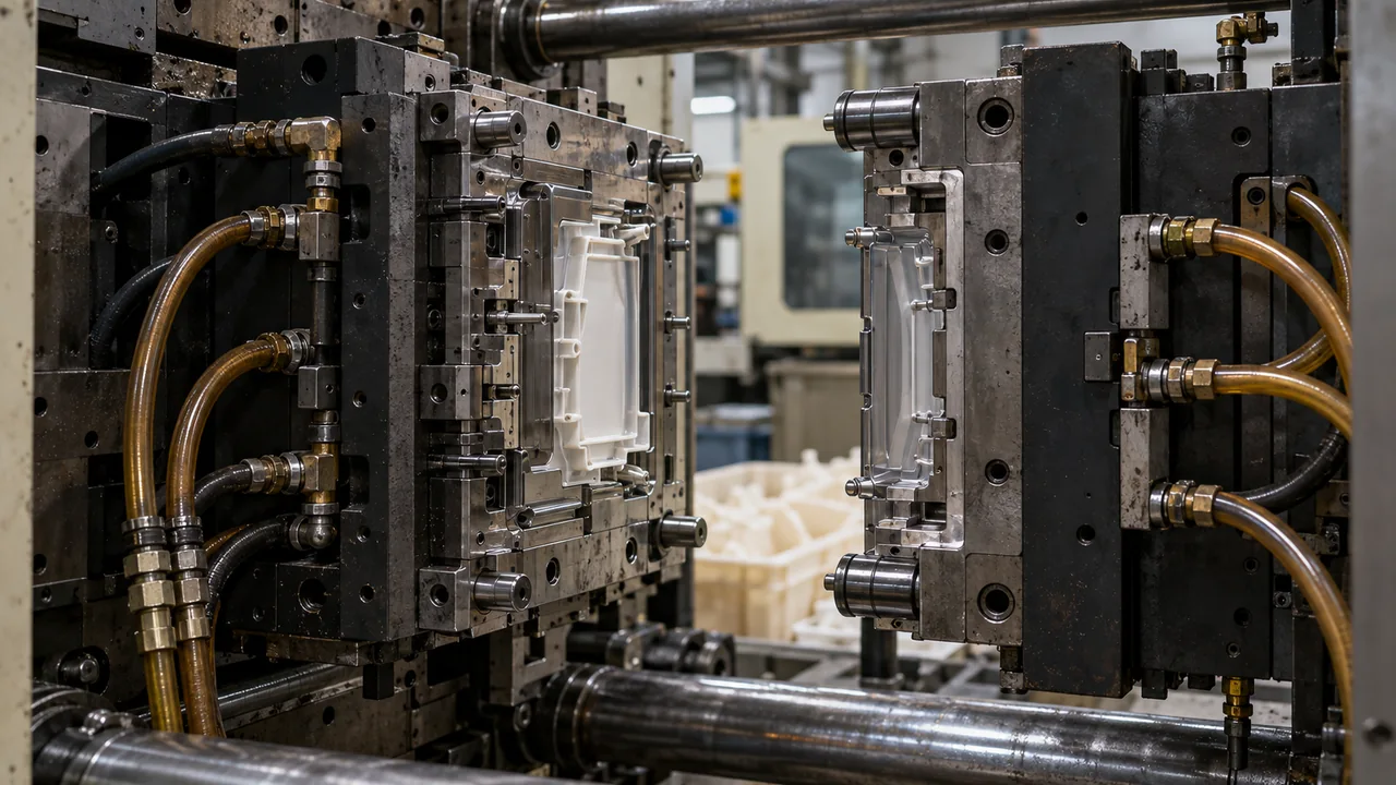
It depends on the required mold temperature and system rating. High-temperature oil or electric heating is often considered where water systems cannot safely reach the needed surface temperature. Water heating is limited by the rated operating pressure and temperature of the complete system. Confirm the grade requirement and equipment capability before choosing pressurized water, oil or electric heating.
Do filled polymers always require hardened steel?
Abrasive fillers increase wear risk, but steel and insert choices should reflect volume, velocity, geometry, finish and maintenance strategy. Evaluate filler abrasiveness, production volume and wear-critical features together. Hardened or replaceable inserts may be justified locally; the polymer family alone cannot specify the same steel treatment for every tool.
Why insulate the mold from the platen?
Insulation reduces heat loss, improves thermal control and protects machine components from unnecessary heat transfer. Check insulation temperature rating, compressive capability and mounting interfaces. The objective is controlled heat loss without compromising clamp-load support or overheating nearby machine components.