
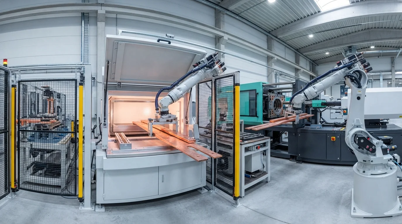
High-voltage distribution in electric vehicle (EV) battery systems requires robust, insulated pathways to connect modular cell stacks safely. Traditional wiring harnesses are bulky, labor-intensive to assemble, and prone to routing errors under high-vibration conditions. Integrating conductive copper or aluminum conductors directly into structural plastic enclosure elements solves these issues while maximizing spatial efficiency. This technical engineering guide addresses the tooling configurations, material science selection criteria, and quality validation processes essential for metal-plastic overmolding.
목차
Solving Thermal Expansion Mismatch in Metal-Plastic Overmolding
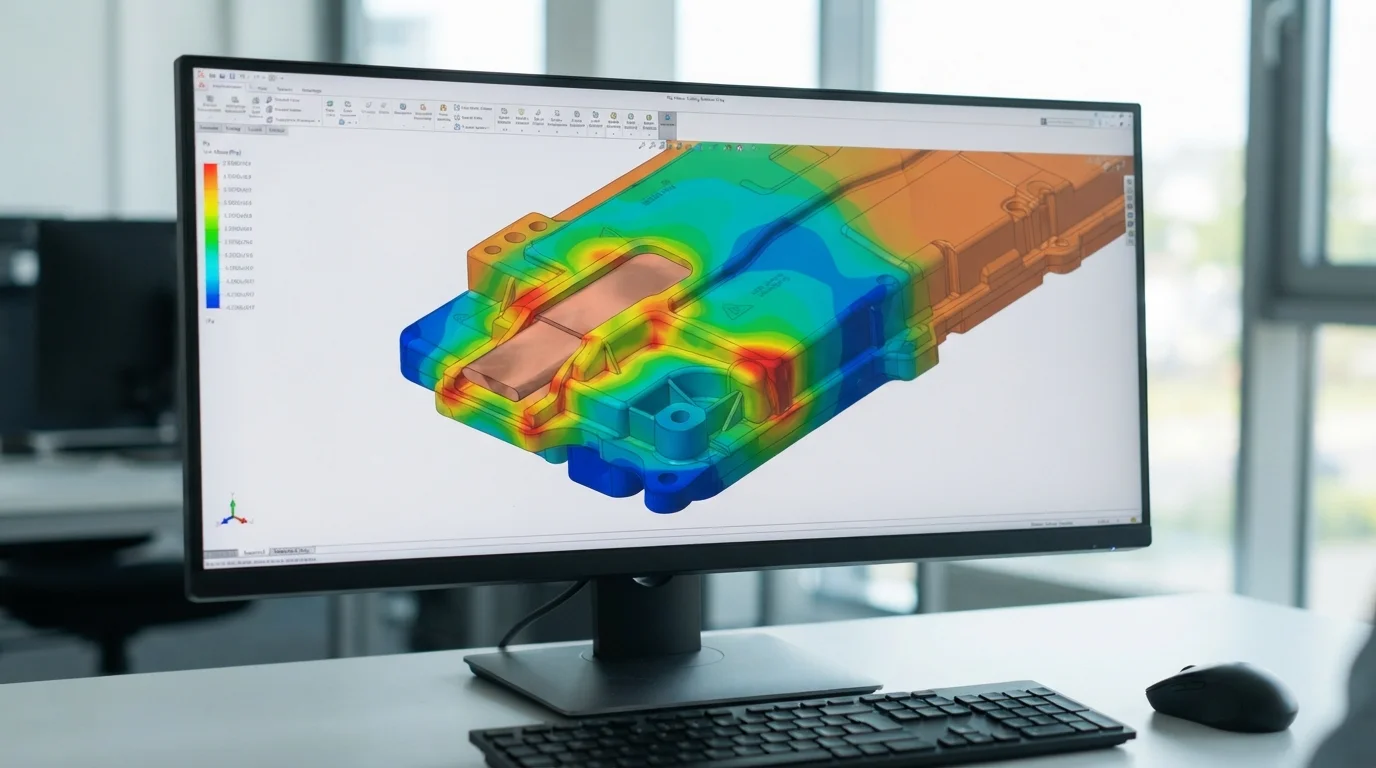
Integrating copper or aluminum busbars directly into the plastic structure simplifies assembly, and performing insert molding busbars in EV battery covers provides a robust insulation layer that prevents short circuits. However, fusing rigid metal and molten thermoplastic introduces severe physical stress because of the vast difference in their coefficients of thermal expansion (CTE). Copper expands at approximately 16.5 ppm/K, whereas typical engineering resins shrink and expand at significantly higher rates. During the cooling phase of the injection cycle, this thermal mismatch causes localized residual stress inside the polymer, potentially leading to micro-cracking around the metallic insert.
To neutralize this mechanical stress, our tooling engineers implement a structured approach:
- 금속 인서트 예열—Warming the copper terminals to 100°C before loading them into the mold core reduces localized thermal shock during polymer injection.
- Optimizing melt holding pressure—Applying multi-stage holding profiles prevents packing stresses from concentrating near the metal-to-plastic boundaries.
- Selecting high-elongation resins—Using custom impact-modified polyamides or custom PBT blends increases physical resilience around sharp metal corners.
- Integrating rounded insert corners—금속 버스바의 모서리를 둥글게 처리하면 물리적 응력 집중점이 주변 플라스틱을 전단하는 것을 방지합니다.
고전압 클리어런스 불량을 방지하는 것은 insert molding busbars in EV battery covers 이러한 중요한 사전 준비 단계에 달려 있습니다. 당사 툴 샵은 모든 금속 셧오프 면을 맞춤 연삭하여 기밀한 밀봉을 보장합니다. 적절한 준비는 부품이 광범위한 자동차 열충격 사이클 테스트를 물리적 열화 없이 견디도록 보장합니다.
고전압 크리피지 및 클리어런스 컴플라이언스 보장
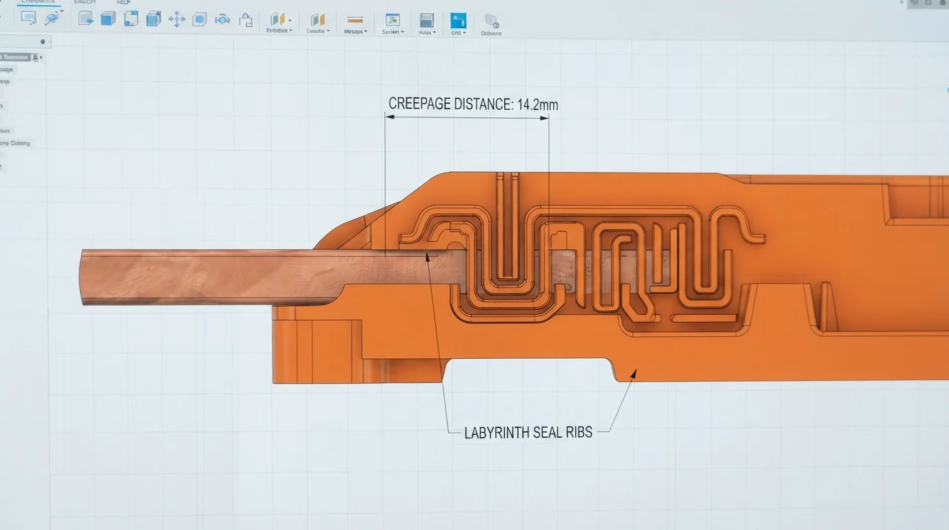
자동차 플랫폼이 400V에서 800V 아키텍처로 전환됨에 따라 엄격한 고전압 안전 컴플라이언스 준수는 필수입니다. 직접적인 플라스틱-금속 계면 설계는 IEC 60664-1과 같은 국제 전기 절연 표준을 엄격히 준수해야 합니다. 습기, 염수 분무 및 대기 중 미립자 침전물은 플라스틱과 금속이 만나는 경계를 따라 전도성 트래킹 경로를 생성할 수 있습니다. 트래킹 불량에 대응하기 위해 툴링 설계자는 노출된 금속 접점의 둘레를 따라 높은 미로형 리브를 통합합니다.
이러한 돌출된 폴리머 장벽은 배터리 팩 커버의 전체 설치 공간을 늘리지 않으면서 물리적 크리피지 거리를 인위적으로 연장합니다. insert molding busbars in EV battery covers 공정 중 폴리머 매트릭스의 차등 수축을 제어하면 이러한 미로 경계를 따라 미세 간극이 형성되는 것을 방지합니다. 0.05mm 간극만으로도 습기가 모여 고전압 누설 또는 치명적인 유전 파괴를 유발할 수 있습니다. 당사는 멀티포인트 인젝션 게이트를 사용하여 캐비티 충전의 균형을 맞추고 금속 기판의 모든 제곱밀리미터에 걸쳐 견고한 물리적 밀봉을 확보합니다.
궁극적으로, insert molding busbars in EV battery covers 에 대한 당사의 입증된 역량은 고급 EV용 맞춤형 플라스틱 배터리 하우징. 제조의 핵심 역량입니다. 이러한 구조적 통합은 무게를 줄이면서 자동화된 최종 팩 조립 라인을 단순화합니다. 절연 버스바를 인클로저 구성 요소에 직접 통합하면 느슨한 와이어가 제거되어 까다로운 중장비 플랫폼의 조립 신뢰성이 향상됩니다.
자주 묻는 질문 (FAQ)
활성 버스바 접촉 패드에 플라스틱 플래시가 형성되는 것을 어떻게 방지합니까?
플라스틱 플래시를 방지하려면 툴링 셧오프 공차를 0.015mm 미만으로 유지해야 합니다. 당사 툴링 설계자는 몰드 코어 내부에 스프링 장착 플로팅 인서트를 사용하여 구리 시트 금속 두께의 변화를 보상합니다. 이 동적 압력 클램핑은 고압 사출 중 활성 연결 단자에 대한 견고한 밀봉을 보장합니다.
800V 버스바 인캡슐레이션에 가장 적합한 절연 수지는 무엇입니까?
폴리아미드 66(30% 유리 섬유, PA66-GF30) 또는 폴리부틸렌 테레프탈레이트(PBT)가 주요 엔지니어링 선택입니다. 이 폴리머는 600V 이상의 우수한 비교 트래킹 지수(CTI) 등급을 제공하면서 동적 진동 하중을 견디는 데 필요한 기계적 강성을 제공합니다.
오버몰드 버스바의 밀봉 무결성을 어떻게 테스트합니까?
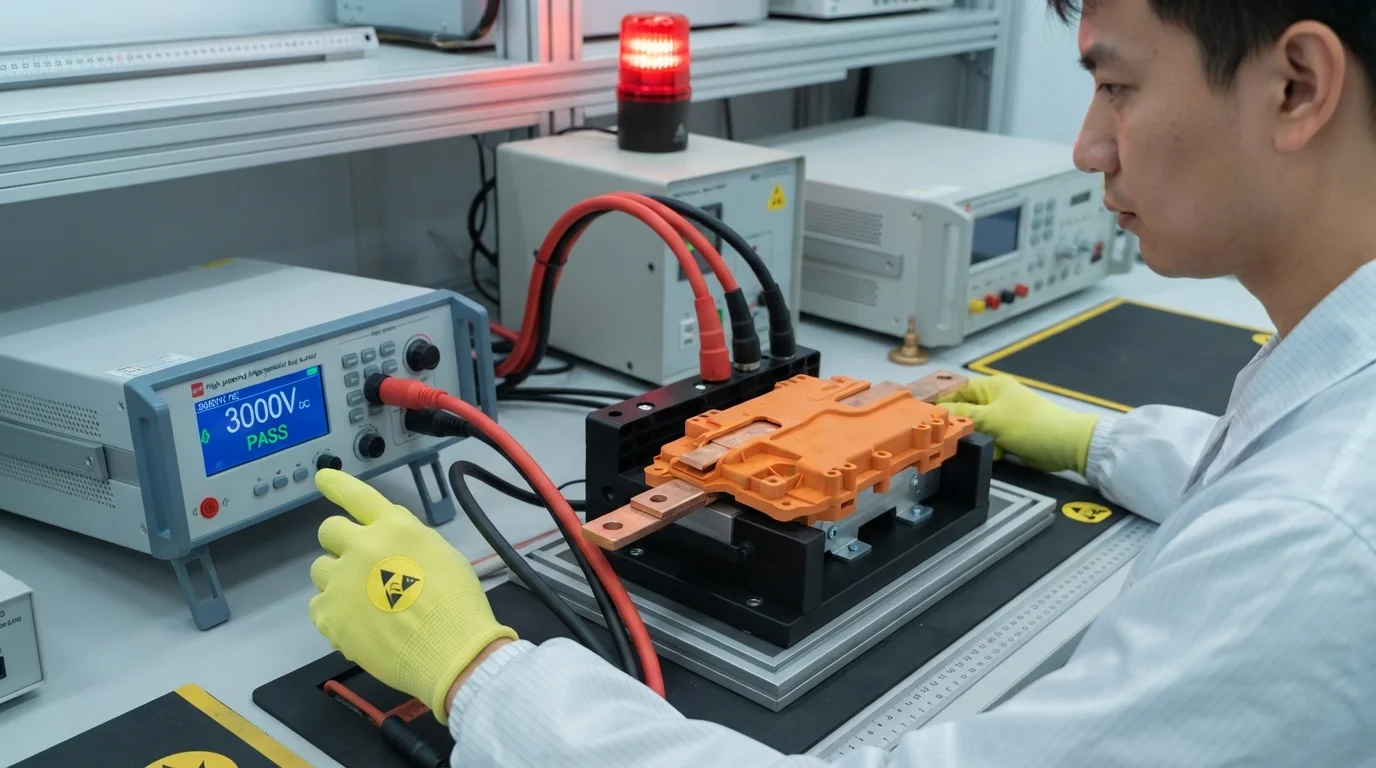
품질 검증은 고압 버블 누출 테스트와 고전압(Hi-Pot) 전기 절연 테스트를 활용합니다. 캡슐화된 구리 전체에 3,000V DC를 인가하여 시뮬레이션 조건에서 유전체 절연 누출이 전혀 없음을 확인합니다.