
Molding metal-plastic hybrid hardware requires precise processing control and tight tooling tolerances to maintain high yield rates. Uncontrolled thermal gradients, improper gate placement, and out-of-spec metal inserts introduce severe quality defects that inflate scrap expenses. Identifying root causes during early pre-production trials prevents field failures and protects downstream automated assembly equipment.

Common processing anomalies range from plastic flash bleeding onto active electrical contacts to environmental stress cracking around embedded metal studs. Tooling engineers and processing technicians must collaborate to diagnose mechanical tool wear, melt rheology variations, and insert alignment drift. This technical troubleshooting guide reviews root causes and corrective engineering actions for primary encapsulation defects.
목차
Resolving Plastic Flash (Over-flash) at Tooling Shut-Off Lands
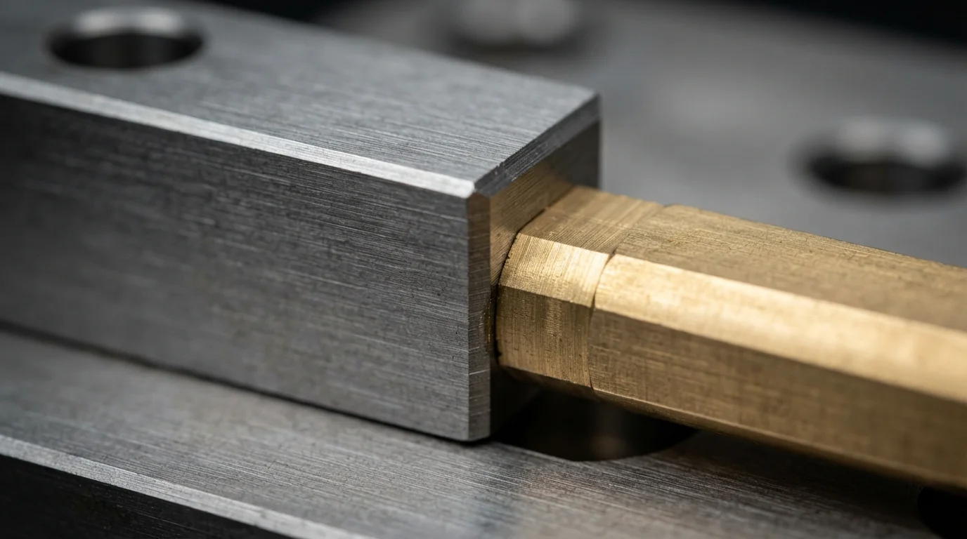
Eliminating frequent insert molding defects requires strict control over mold shut-off steel fitment and insert metal tolerances. Plastic flash occurs when low-viscosity resin bleeds past cavity sealing lands onto active terminal contacts or internal threads. Dimensional variations in pre-stamped 황동 or copper inserts represent the primary cause of shut-off seal leakage.
Oversized metal inserts crush tool steel shut-off faces upon mold clamp-up, destroying shut-off land flatnesses permanently. Undersized inserts leave micro-gaps that permit molten polymer to bleed onto contact pads under high packing pressure. Tooling engineers integrate spring-loaded floating core shut-offs that compensate dynamically for metal insert thickness variations, creating a flash-free seal.
| Primary Molding Defect | Root Cause Mechanism | Tooling Engineering Fix | Process Parameter Tuning |
|---|---|---|---|
| Plastic Flash on Terminal Contacts | Insert thickness variation or crushed shut-off lands | Incorporate spring-loaded floating core shut-offs | Reduce second-stage holding pressure & clamp force |
| Boss Cracking Around Metal Inserts | CTE mismatch & high thermal shock gradients | Increase boss wall thickness & round internal radii | Preheat metal inserts to 100°C before loading |
| Insert Displacement / Pin Tilting | Unbalanced hydrodynamic melt fill pressure | Add core locating pins & magnetic core locks | Implement multi-stage velocity fill profiling |
Eliminating Plastic Cracking Caused by Thermal Shock & Residual Stress
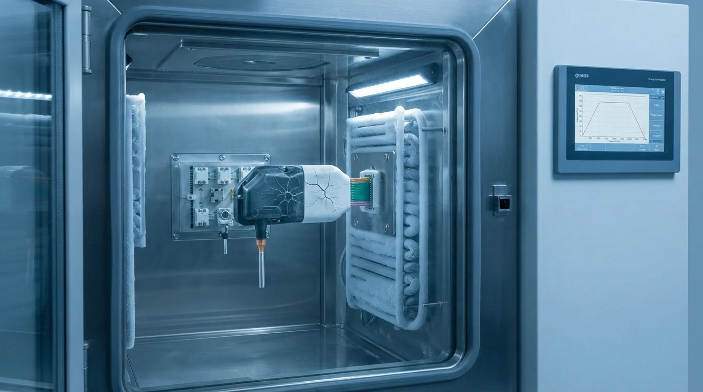
Polymer stress cracking around metallic fasteners stems from high molded-in residual stress and Coefficient of Thermal Expansion (CTE) mismatch. Metals contract significantly slower than cooling thermoplastics like PA66, PBT, 또는 PC/ABS, creating intense hoop stress inside surrounding boss walls.
High shear rates generated at narrow gates cause localized polymer degradation, increasing notch sensitivity along metal corners. Subjecting the component to environmental thermal shock or chemical electrolyte vapors triggers rapid stress cracking. Preheating metal inserts to 100°C before loading lowers thermal gradients during primary 인서트 몰딩, while post-mold annealing relaxes residual molecular tension.
Preventing Insert Movement and Weld Line Weakness
Preventing insert displacement during filling depends on robust mechanical retention built into the mold tool. High-velocity melt fronts exert substantial hydrodynamic forces capable of tilting unanchored electronic pins or shifting threaded studs. Integrating hardened 로케이팅 핀, core magnets, or pneumatic clamping slides holds inserts securely during high-pressure packing.
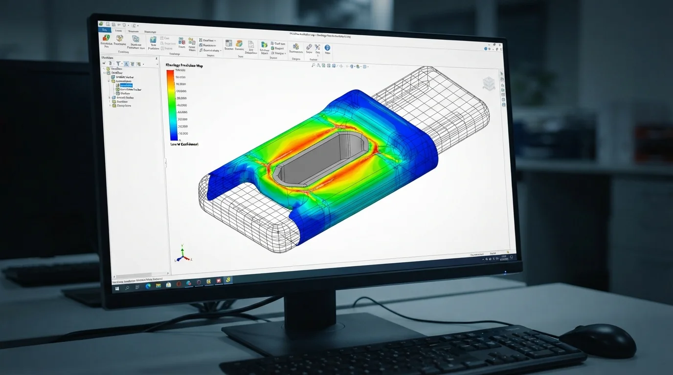
Weak weld lines form when separate polymer melt streams flow around a metal insert and recombine on the trailing side. Reduced melt temperature at the flow front prevents complete molecular interdiffusion, creating a structural weakness. Utilizing Moldflow 시뮬레이션 software allows engineers to optimize gate placement, moving weld lines to non-structural regions and increasing weld strength.
Key defect prevention sequence includes:
- Metal insert preheating—Warming metal fasteners to 100°C reduces thermal shock during polymer contact.
- Core locating pin engagement—Securing inserts onto ground locating pins holds components true during high-velocity filling.
- Multi-stage pressure profiling—Decelerating melt velocity near inserts reduces hydrodynamic displacement forces.
- Post-mold thermal annealing—Baking molded components in industrial ovens relaxes internal hoop stresses surrounding inserts.
자주 묻는 질문 (FAQ)
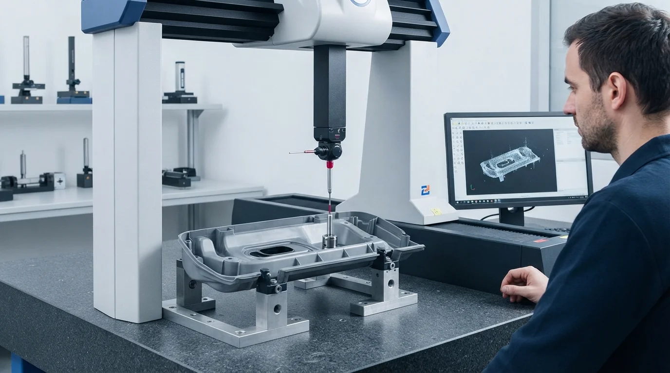
What causes plastic flash on brass threaded inserts during insert molding?
Plastic flash occurs when dimensional variations in metal inserts leave micro-gaps between the insert shoulder and mold shut-off steel. High packing pressure forces molten resin into these gaps, coating the threads. Spring-loaded floating core pins and precision shut-off land grinding prevent flash formation.
How do you prevent plastic boss cracking around metal inserts?
Preventing plastic cracking requires preheating metal inserts to 100°C prior to molding to minimize thermal shock during cooling. Designing boss wall thicknesses to 2.0 to 2.5 times the insert outer diameter provides sufficient plastic mass to absorb localized hoop stresses.
How does Moldflow simulation help prevent insert movement defects?
Moldflow simulation models hydrodynamic melt velocity vectors and pressure distribution inside the cavity. Analyzing flow fronts allows tooling engineers to position gates symmetrically around the metal insert, balancing filling forces and preventing insert tilt during injection.