
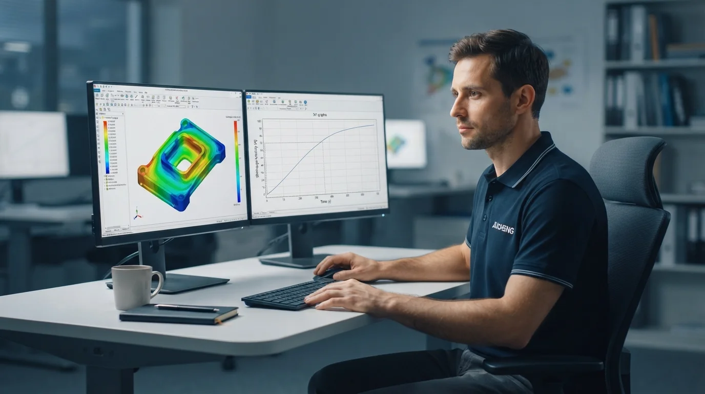
Optimizing injection mold tooling before cutting tool steel eliminates high-risk engineering trial-and-error cycles. Unexpected air traps, cosmetic weld lines, localized sink marks, and post-mold warpage can delay product launches by weeks while inflating non-recurring engineering budgets. Computer-aided engineering (CAE) rheology software simulates molten polymer behavior inside heated cavities, allowing tooling engineers to validate part geometries virtually. This technical guide reviews filling dynamics, pack-pressure profiling, fiber orientation mapping, and gate position optimization.
目次
Moldflow CAE Simulation: Fill, Pack, Warp & Fiber Orientation
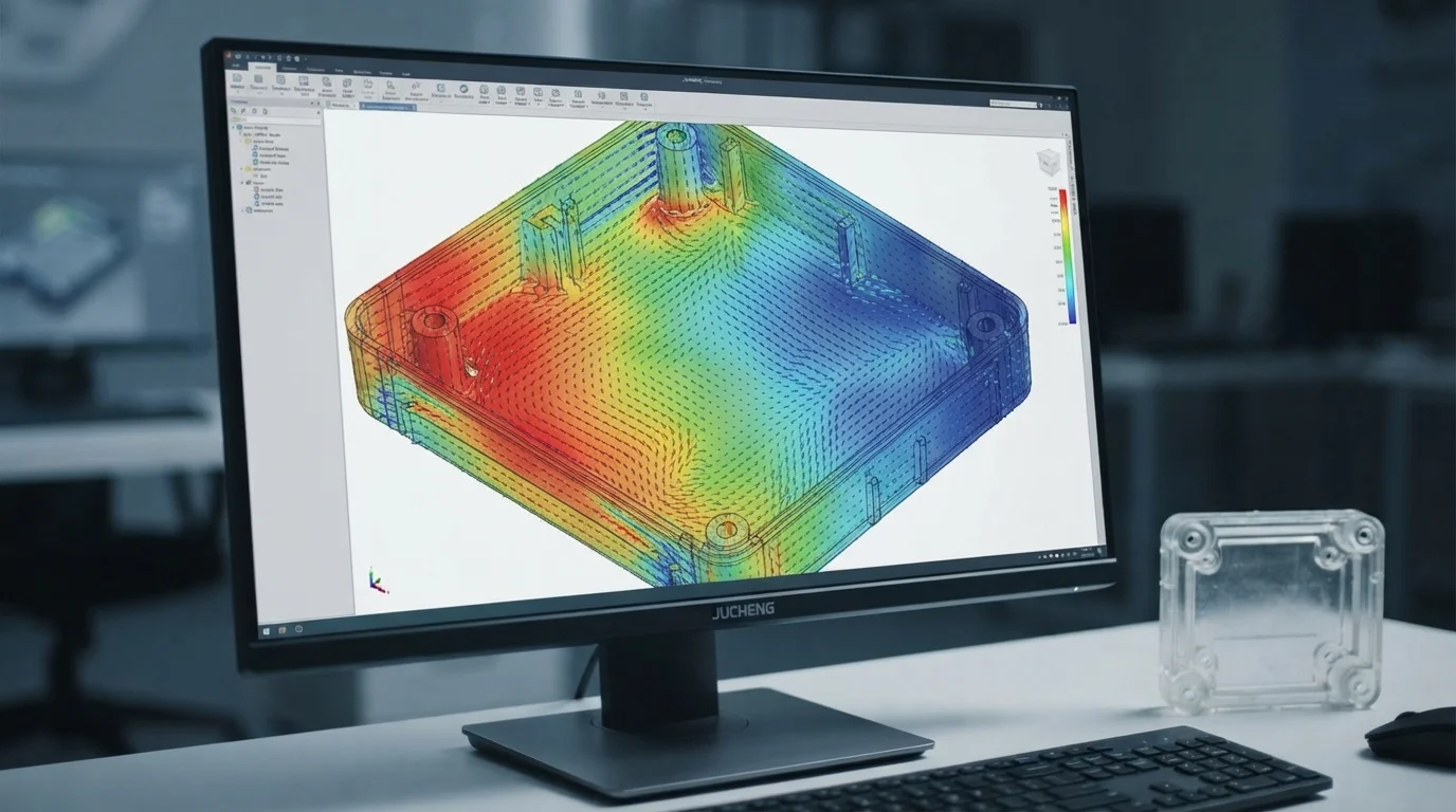
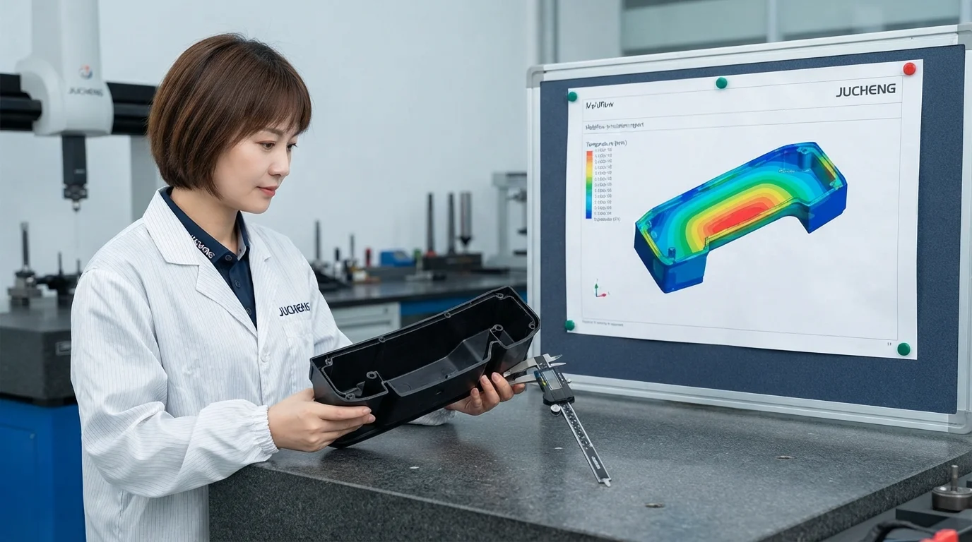
Executing comprehensive モールドフロー解析 using CAE Moldflow simulation models the exact fluid mechanics of molten thermoplastics inside complex mold cavities. Simulation algorithms calculate volumetric shrinkage, melt pressure drop, cooling time distributions, and part warpage prior to tool steel cutting. Modeling glass-reinforced engineering thermoplastics like PA66-GF30 または PEEK maps 異方性収縮 繊維が流動経路に沿って配向することで生じるベクトル。方向性のある繊維配向を予測することで、構造用バッテリートレイや大型自動車パネルにおける成形後のねじれを防ぎます。バーチャルプロトタイピングにより、ツール設計が初期T1トライアルから広く安定した加工ウィンドウを確立できることを保証します。.
シミュレーション解析機能には以下が含まれます:
- 充填相モデリング—メルトフロントの進行速度を予測することで、マルチドロップランナー全体にわたるバランスの取れたキャビティ充填を保証します。.
- 保圧プロファイリング—保持圧力分布をシミュレーションすることで、ひけ跡や局所的な過充填を防ぎます。.
- 冷却回路最適化—コアとキャビティの熱抽出を解析することで、反りを引き起こす熱的ホットスポットを特定します。.
- 反り予測マッピング—成形後の変形ベクトルを計算することで、エンジニアは事前補正されたキャビティオフセットで工具鋼を切削できます。.
ウェルドライン、エアトラップ、ひけ跡の予測と排除
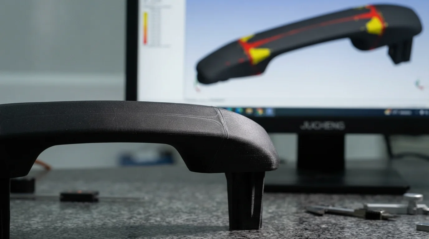
予測 ウェルドライン位置 およびエアトラップを金属切削前に予測することで、外観面と構造的完全性を保護します。ウェルドラインは別々のポリマー流動フロントが出会う場所に形成され、部品の引張強度を弱める機械的ニットラインを生じさせます。レオロジーシミュレーションにより、エンジニアはゲート数やゲート位置を調整し、ウェルドラインを非外観領域や低応力領域へ移動させることができます。圧縮されたエアトラップを特定することで、必要なマイクロベント位置が明らかになり、高速充填時のディーゼルバーン欠陥を防ぎます。構造リブとスクリューボスのモデリングによりリブ対壁の比率を検証し、外観面への外観上のひけ影を防ぎます。.
高L/T比樹脂におけるゲート位置と射出圧力の最適化
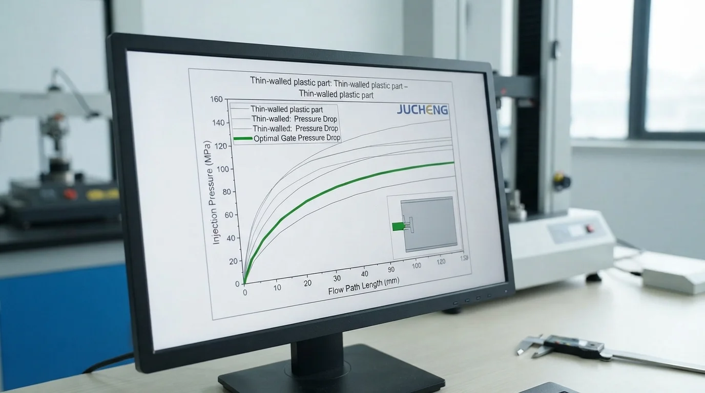
ゲート位置の選定は、キャビティ充填の対称性と必要なプレス型締めトン数を決定します。高粘度樹脂から成形される高流動長対厚み(L/T)比部品は、例えば PC/ABS 過剰な射出圧力降下を防ぐために最適化されたゲート断面積を必要とします。レオロジーシミュレーションは正確な射出圧力を計算し、機械のトン数過負荷を防ぎます。ゲート寸法を評価することで、せん断速度が安全限界内に保たれ、難燃添加剤を熱劣化から保護します。包括的なモールドフロー解析を実施することで、工具鋼の機械加工が始まる前にランナー径とノズルオリフィスサイズを最適化します。.
| シミュレーション解析タイプ | 予測データ出力 | 金型エンジニアリングアクション | 主要な品質上の利点 |
|---|---|---|---|
| フローフロント充填時間 | メルトフロント進行コンター | ホットランナーゲートサイズのバランス調整 | ショートショットと過充填を排除 |
| ウェルドライン・エアトラップマップ | フローフロント収束角度 | ゲートの再配置またはベントの追加 | ウェルド強度を最大化し痕を隠す |
| 体積収縮と反り | 3Dたわみベクトルオフセット | 金型コア鋼の事前補正 | 成形後の組立平坦度を保証 |
よくある質問 (FAQ)
切削工具鋼の加工前に金型流動解析を実施すべき理由は何ですか?
工具製作前に金型流動解析を実施することで、部品形状がまだデジタルデータの段階で構造的・外観的リスクを特定できます。ウェルドライン、エアトラップ、過度な反りを早期に検出することで、エンジニアは高額な鋼材の再加工なしにゲート位置や肉厚を修正できます。仮想シミュレーションにより高歩留まり生産が確保され、長期間の工具遅延を防ぐことができます。.
金型流動シミュレーションはガラス繊維強化ポリマーの反りをどのように予測しますか?
ガラス繊維は溶融樹脂の流動フロントに平行に配向し、プラスチックが流動ベクトルに沿う方向と直交する方向で異なる収縮をする異方性収縮を引き起こします。金型流動ソフトウェアは、部品の平方ミリメートルごとに正確な繊維配向マトリックスをシミュレーションします。これらの方向性収縮差を計算することで成形後の変形を予測し、金型製作者が金型キャビティ鋼を事前補正できるようにします。.
標準的なMoldflowシミュレーションレポートにはどのような重要情報が含まれますか?
標準的なMoldflowレポートには、充填時間アニメーション、射出圧力分布、流動フロント温度、ウェルドライン位置マッピングが含まれます。レポートはまた、エアトラップ位置、体積収縮率、推定総部品たわみを強調表示します。これらのデータセットを確認することで、エンジニアリングチームはT1サンプリング前にプロセスウィンドウを最適化できます。.