
A gas assist injection molding design guide should begin with one question: can gas travel through the intended thick section without escaping into a thin wall or stopping early? The answer depends on the relationship among the resin gate, gas entry, channel geometry and cooling path. A hollow handle can look simple in CAD, yet a branch, abrupt thickness change or uninspectable end can turn a promising concept into a difficult mold trial.
The guide below is for product and mold engineers deciding what to resolve before steel is cut. The broader stampaggio a iniezione assistito da gas page covers the available process and part types. Here the focus is the design evidence that makes the intended gas path plausible and testable.
Design review route
- Draw the path before sizing the rib
- Align resin flow and gas entry
- Control transitions and branches
- Plan how the channel will be checked
- A pre-tooling review checklist
- Design questions
Draw the Hollow Path Before Sizing the Rib
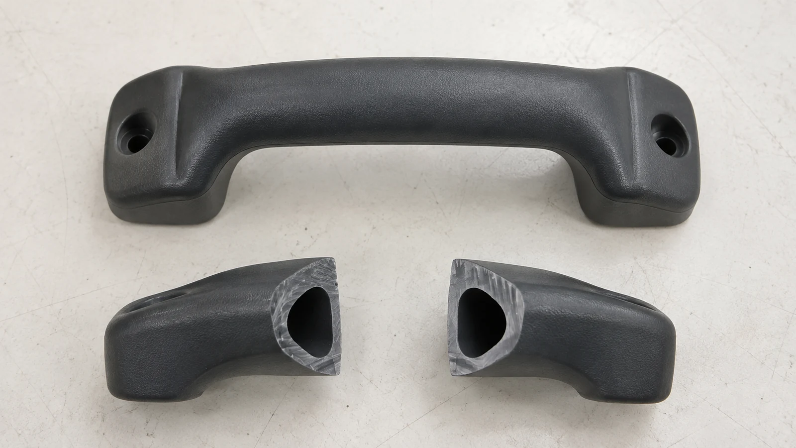
Start by tracing where the gas should enter, which thick feature it should hollow and where penetration should end. A long handle or structural rib offers a clearer candidate route than a broad flat wall with no defined thick section. The channel is a product feature, not merely a mold setting: it changes local wall thickness, cooling and the way a load passes through the finished part.
Mark load-bearing areas, visible faces, fasteners and any region that must remain solid. Then compare the intended route with those restrictions. If the part needs a controlled solid boss at the end of a hollow handle, that transition needs a deliberate location and a way to verify it. If the gas path would cross a critical hole or thin a corner under load, revise the geometry before debating pressure settings.
Simulation can identify likely penetration and filling problems, but its usefulness depends on the model representing the channel and adjacent walls accurately. Autodesk’s Moldflow guidance treats gas-channel geometry and local mesh detail as material to the prediction. For a complex route, dell'analisi del flusso nello stampo is most useful when paired with marked cross sections and trial evidence rather than treated as a certificate of performance.
The Resin Gate and Gas Entry Must Tell the Same Flow Story

A channel can be continuous in the CAD model yet fail if the melt reaches it unevenly. Map the expected resin front from the gate before choosing a gas pin or nozzle location. Gas introduced too close to an unintended hot pocket may take that easier route, while a poorly located entry can leave the far end solid. Neither outcome is solved simply by drawing a thicker rib.
Review gas entry together with gate vestige, cosmetic faces, parting line, access for maintenance and the direction in which displaced resin can move. A hidden underside may be more tolerant of an entry mark than a visible face, but the location still has to support the required penetration. The correct position depends on the part and mold; it is not a fixed distance or a universal rule.
A useful design meeting therefore puts the part section, gate location, proposed gas entry and melt-flow direction on the same drawing. When these appear on separate slides, conflicts are easy to miss until the first cut part is examined.
Transitions and Branches Decide Whether the Gas Stays on Course
Gas favors the hotter route with lower flow resistance. An abrupt turn or an ambiguous fork can produce uneven penetration, leaving one branch solid while another becomes too thin. A channel that grows excessively large can act as a flow leader during resin filling and alter the fill of nearby thin sections. A very weakly defined channel may fail to guide gas at all.
Use smooth transitions where the hollow feature joins the nominal wall, and identify every branch that expects gas to divide. The right proportions depend on resin behavior, geometry and the desired remaining wall, so avoid copying a single channel-to-wall ratio from another product. A review should ask which features are genuinely required for stiffness and which merely preserve the shape of an earlier solid design.
If the concept requires a closed loop or multiple equally filled branches, challenge that assumption early. Small differences in flow and temperature can cause gas to choose one path first. A simpler, inspectable route may be more robust than a geometrically elegant network.
Design the Inspection Plan While the Part Is Still in CAD
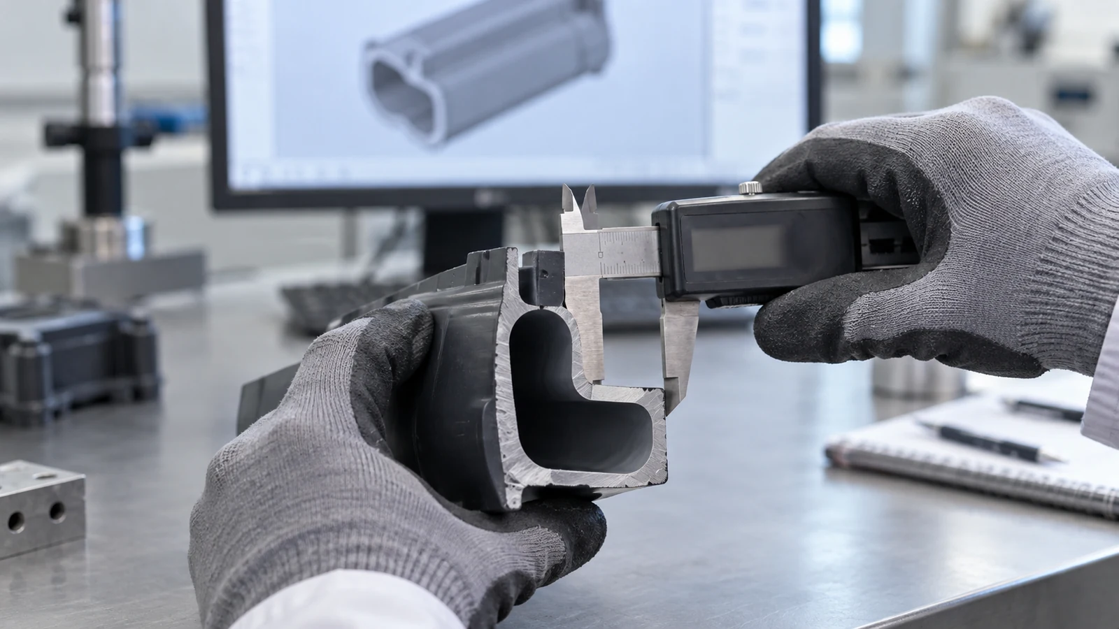
A hidden channel cannot be approved by appearance alone. Choose section planes at the entry, a bend or branch, and the far end. For parts whose function depends on remaining wall thickness, agree on the load case and inspection method before making trial samples. A cut part can show where gas penetrated; it does not by itself establish long-term strength or dimensional stability.
Keep the inspection drawing and the part drawing synchronized. If a channel changes during tooling review, the section locations and acceptance criteria may need to change too. This is a practical reason to carry the hollow route through progettazione professionale di stampi a iniezione rather than attaching it as a late processing note.
Five Questions to Close Before Cutting Steel
- What is the exact intended gas route? Mark its start, bends, branches and termination on the 3D model.
- Which surfaces and sections must stay solid? Identify cosmetic, fastening and load-bearing regions that gas must avoid.
- Do gate and gas entry support the route? Review melt front, gas entry mark and displaced-resin path together.
- Can cooling change the route? Check thick-to-thin transitions and local thermal imbalance.
- How will the result be proven? Specify cut planes, dimensions and any functional test required by the drawing.
If several answers are still assumptions, the design is not ready to be judged only on a quoted cycle time or expected material saving. Those outcomes depend on a repeatable channel and a part that passes its actual requirements.
Design Questions Worth Settling Early
Can an existing solid-part mold simply be converted to gas assist?
Sometimes, but it should not be assumed. The part needs a suitable thick path and the mold needs a workable gas entry, vent or release strategy, and access for maintenance. Geometry changes may be more important than adding gas hardware.
Does every thick rib need to become hollow?
No. A rib can serve stiffness, mounting or flow purposes. Hollowing should be tied to a specific sink, weight, filling or cooling problem and checked against the required remaining wall.
What should accompany a design review request?
Send the CAD model, drawing, resin specification, marked appearance faces, critical loads and the proposed hollow route. If an earlier sample exists, include photographs and section cuts with their locations identified.