
Side action vs. lifter injection mold design is a choice about how an undercut is released, not just which moving component is smaller. A side action commonly retracts laterally from the cavity before the mold opens or the part is ejected; a lifter moves along an angled path with the ejector system to release a feature as the part advances. The actual motion and timing depend on the tool architecture.
Start with the direction of the undercut relative to the primary mold opening. Then check the part’s clearance, cosmetic surfaces, available tool space, and how the feature will be inspected and maintained. A mechanism that releases the geometry in CAD may still be difficult to cool, vent, or service in a production tool.
Identify the motion the feature needs
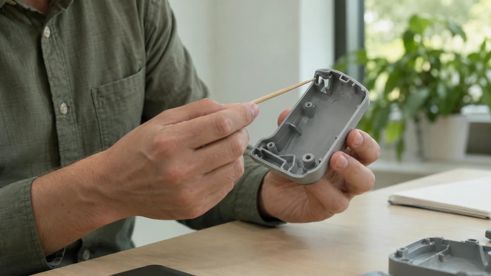
Mark the undercut on the CAD model and show the direction it must move to clear the molded part. A side-facing hole, slot, or latch may need a core that withdraws across the parting direction. An internal hook or recessed feature may be easier to release with a lifter that follows the ejector stroke. These are starting points, not rules; the feature’s exact shape and the rest of the tool can change the answer.
Also identify whether the feature is functional or cosmetic. A latch may need a clean lead-in and predictable engagement, while a side port may need a sealing land and controlled position. The mechanism must release the undercut without dragging across those surfaces or leaving an unacceptable witness mark.
Compare the two mechanisms against the part and tool
Review each option for travel, clearance, shutoff surfaces, and access for maintenance. The table frames the discussion; a detailed tool layout should confirm the real motion envelopes and interactions.
| Decision point | Side action to review | Lifter to review |
|---|---|---|
| Undercut direction | Can a core withdraw laterally before the part is released? | Can the angled travel clear the feature during ejection? |
| Available space | Is there room outside the cavity for the slide, drive, and return? | Is there room behind or beside the ejector system for the lifter path? |
| Part surface | Will the core shutoff or slide mark affect a visible or sealing face? | Could the angled motion rub, drag, or distort a delicate feature? |
| Service access | Can the slide, wear surfaces, and drive be inspected and maintained? | Can the lifter and its guides be reached for inspection and replacement? |
A side action may add space and motion outside the main mold opening; a lifter may couple undercut release with ejection and require careful travel and clearance planning. Neither automatically guarantees a cheaper, faster, or more reliable mold. Use the part geometry and maintenance plan to compare the proposals during injection mold design.
Check the surrounding part geometry
Before choosing a mechanism, review the wall around the undercut, the draft on adjacent faces, the direction of expected load, and the available room for the moving core. A feature may be simplified by changing its opening direction, adding a split line, or revising a latch or slot so it can be formed with a less complex motion. Any change must preserve the assembly function and customer-facing appearance.
Check where the parting line and gate could sit relative to the moving feature. A core that needs a robust shutoff may conflict with a cosmetic boundary or a critical datum. Venting and cooling access also need review. A DFM discussion should record which risks are resolved by geometry, which depend on the tool layout, and which require verification during a design-for-manufacturing review.
Resolve motion and maintenance before steel
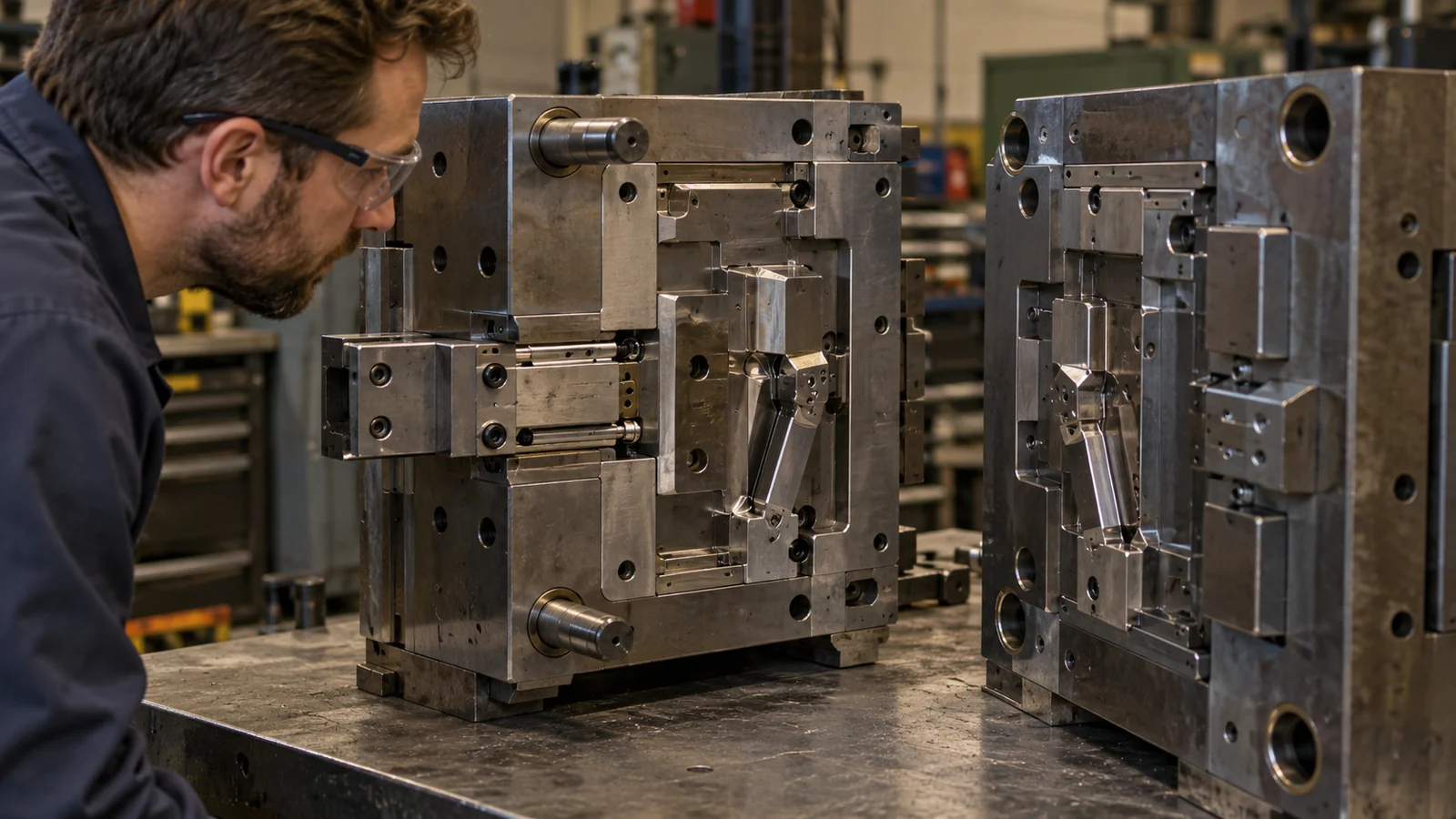
Ask for a motion sequence or section view showing the mold closed, the side action or lifter at full travel, mold opening, and part ejection. Confirm what drives and returns each component, what prevents collision, and how the part clears the undercut. The tool team should also state which wear surfaces and shutoffs require periodic inspection.
At the first trial, verify the intended release sequence, the molded feature, the surrounding surface, and the part’s functional engagement. Record any adjustment and recheck the feature after the tool reaches its normal operating condition. A proposed mechanism is not validated merely because it moves freely without a molded part. Use injection mold trial and validation to confirm the tool and part together.
FAQ
Is a side action always used for external undercuts?
No. Feature direction, mold layout, and available clearances determine the mechanism. A side action is one common solution, but the tool designer should compare the full motion path with the part geometry.
Are lifters only for internal undercuts?
Lifters are commonly considered for features released along an angled path during ejection, often internal geometry. The specific application depends on travel, clearance, and how the part releases from the tool.
Which option is easier to maintain?
There is no universal answer. Compare access, wear surfaces, lubrication or service requirements, and the tool’s actual motion sequence before selecting the mechanism.