
Micro connector injection molding has one unforgiving outcome: a small molded shift can misalign a terminal, weaken a latch, disturb a seal, or prevent mating. Buyers therefore need more than a resin and cavity count. The tool datum scheme, flow path, warpage control, terminal relationship, ejection, and inspection method must all protect the connector’s assembled position.
This article follows the failure chain from mating interface to molded cavity so the design review focuses on what creates open circuits, unstable contact, or assembly rejection.
Review map
Fine Pitch Turns Small Shifts Into Assembly Failures
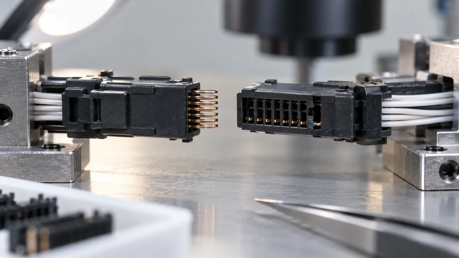
Connector performance depends on relationships: terminal centerline to housing datum, cavity wall to seal, latch to mating shoulder, and coplanarity across contact positions. When pitch becomes small, normal sources of variation occupy more of the available clearance.
Start by defining the worst credible mismatch between the male and female sides. Include molded housing variation, stamped or machined terminal variation, insertion position, fixture error, and mating alignment. Tightening every molded dimension is rarely the best response; it can increase cost without controlling the actual stack.
Functional requirements should identify contact retention, insertion force, withdrawal force, sealing, creepage and clearance where applicable, and permitted cosmetic witness zones. These items guide which features deserve the most capable tooling and inspection.
Build the Datum Scheme Around the Mating Interface
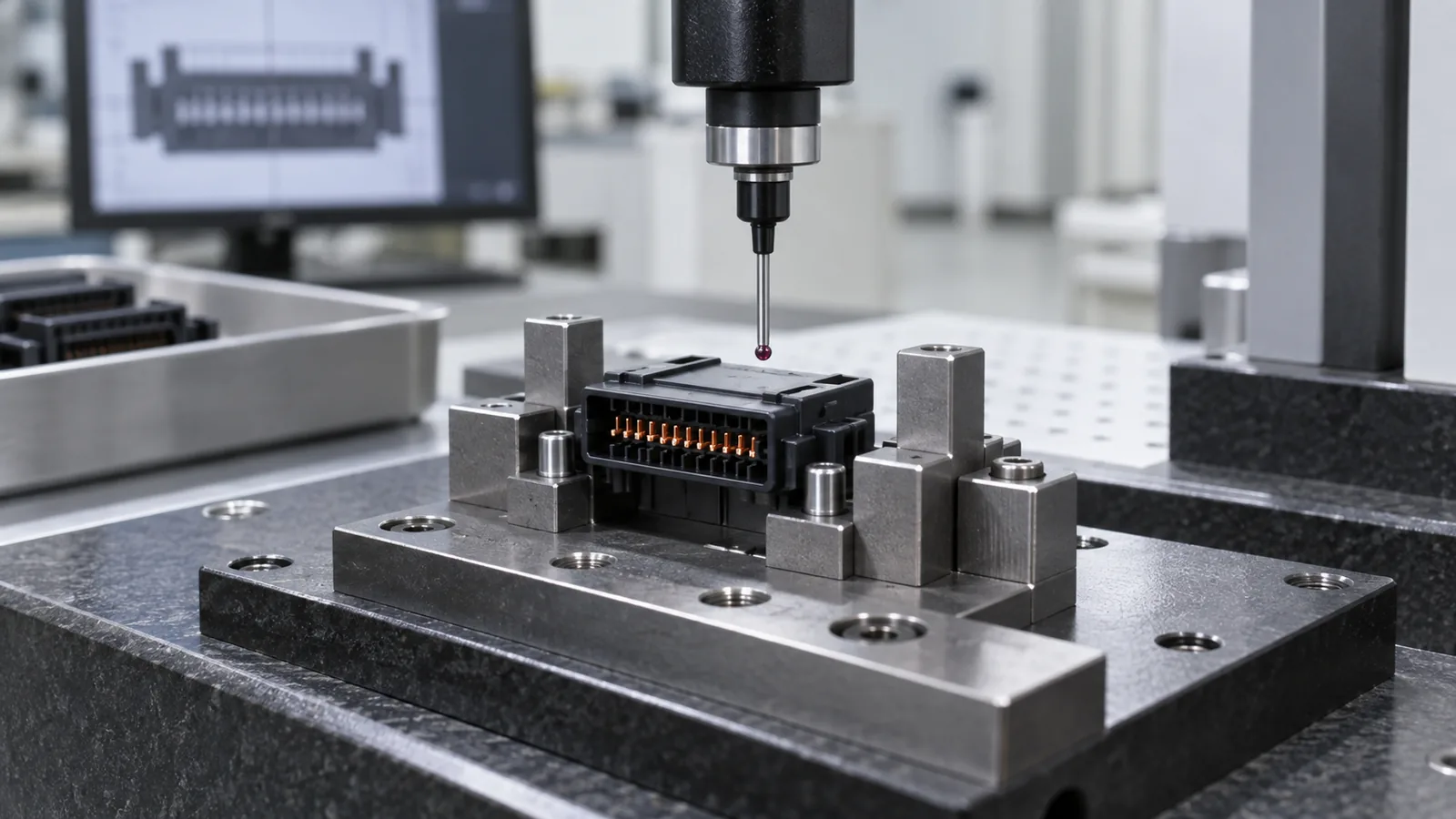
A datum should represent how the connector is located in assembly. If inspection references a broad outer wall while the mating part references an internal key and terminal plane, acceptable inspection results can still produce poor fit.
Map the datum chain from cavity insert and core pin to molded feature, terminal insertion fixture, and final mating interface. Avoid unnecessary chains across flexible walls. Where possible, place functional locating surfaces near the features they control so shrinkage and warpage travel a shorter distance.
Tool inserts can isolate critical geometry and make maintenance practical, but their alignment and shutoffs become part of the tolerance stack. The custom mold making review should identify which steel components establish pitch, terminal windows, latch position, and seal boundaries.
Keep Flow Fronts Away From Critical Contact Features
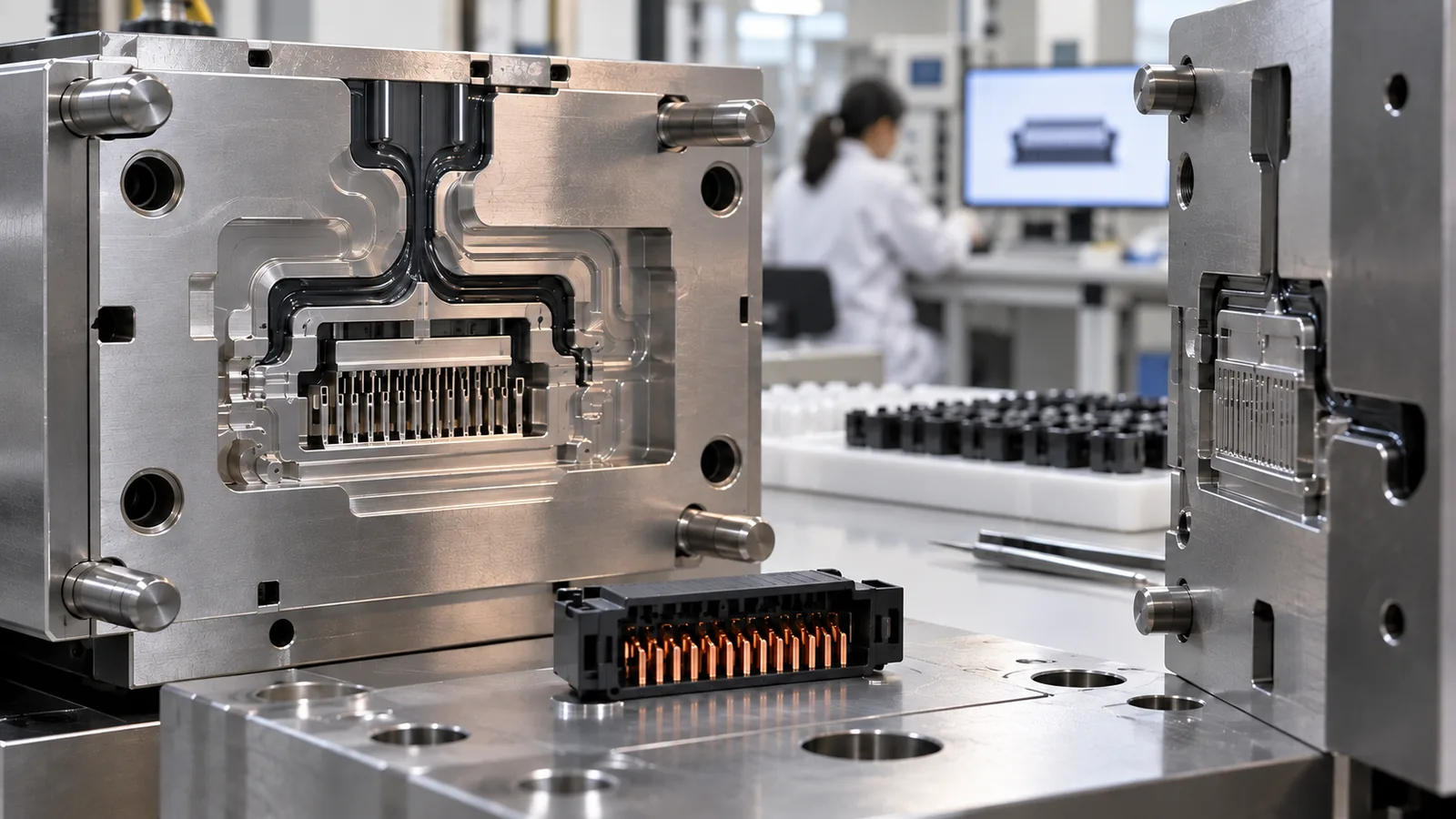
Melt fronts that split and reunite can form weld lines. Trapped gas can create incomplete ribs or burning. A gate may fill the housing successfully while still placing a weak or visually unstable region across a latch, terminal retention feature, or sealing surface.
Review fill order rather than gate distance alone. The flow front should reach fine windows and thin bridges before they freeze, while air escapes at the actual last-fill locations. A focused mold flow analysis can compare gate options and likely air traps before steel is finalized. If flow converges around terminal openings, evaluate whether the resulting line affects strength or dimensional stability.
| Observed risk | Likely contributors | Evidence to compare |
|---|---|---|
| Incomplete terminal window | Freeze-off, gas trap, gate imbalance | Short-shot sequence and vent condition |
| Flash near contact cavity | Shutoff wear, alignment, local pressure | Cavity map and tool contact pattern |
| Weak latch | Weld line, orientation, geometry, material | Fracture location and force test |
Manage Warpage Across Thin Connector Walls
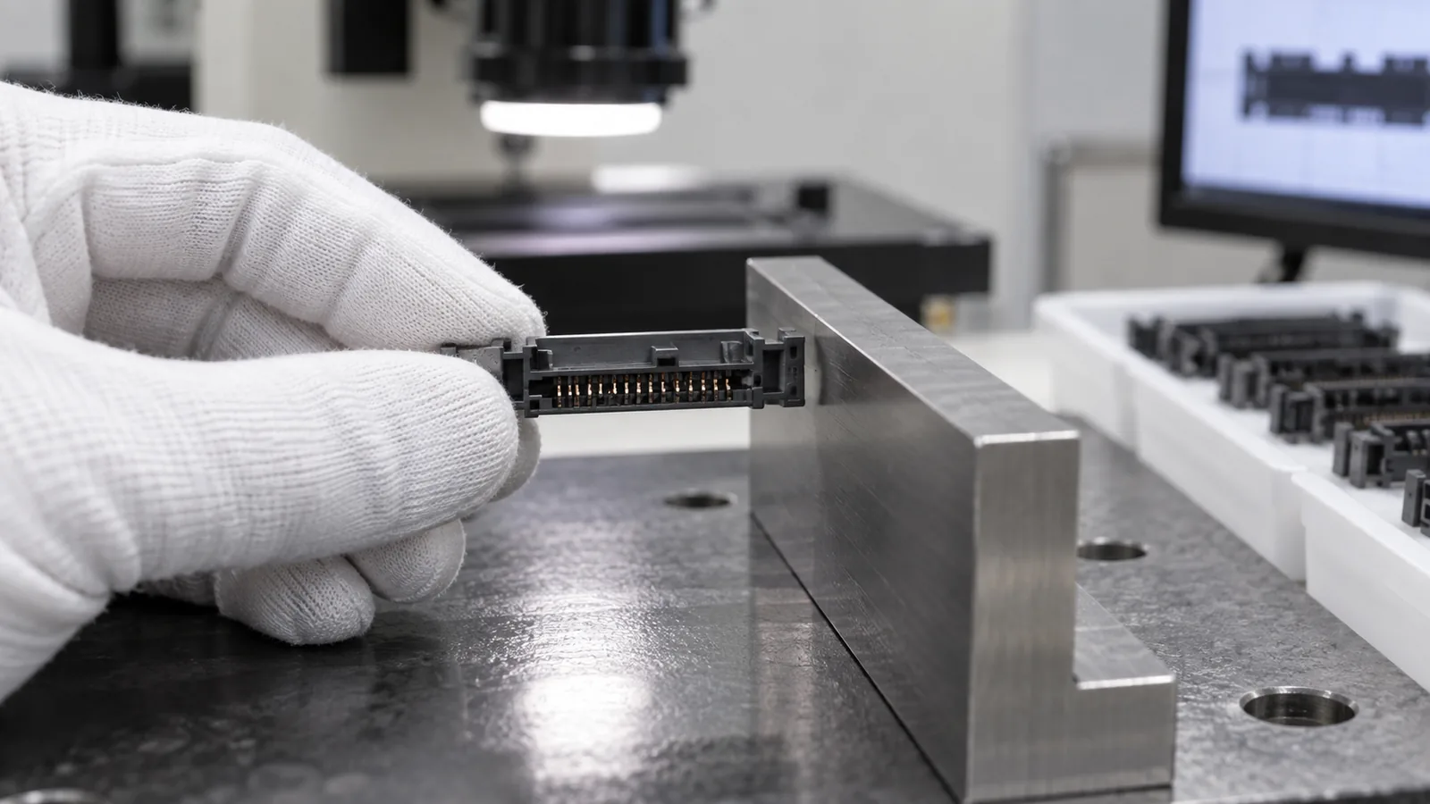
Thin walls and asymmetric features can cool and shrink unevenly. Fiber-filled materials add directional behavior, while terminal openings and latches interrupt otherwise uniform sections. For high-temperature fine-pitch designs, the LCP material family may enter the shortlist, but its flow orientation and the specific grade still require validation. Warpage can change pitch or sealing even when each local wall thickness appears reasonable.
Balance the geometry where product function permits, then use gate location and cooling to reduce directional effects. Packing should be evaluated carefully: excessive local packing may improve one dimension and worsen another. Mold temperature balance and part support after ejection are equally important.
Measure the connector in a free state and, when relevant, in its assembly fixture. A compliant housing may move into position during mating, but that should be an intentional design allowance rather than an accidental correction.
Design Ejection Around Pins and Latches
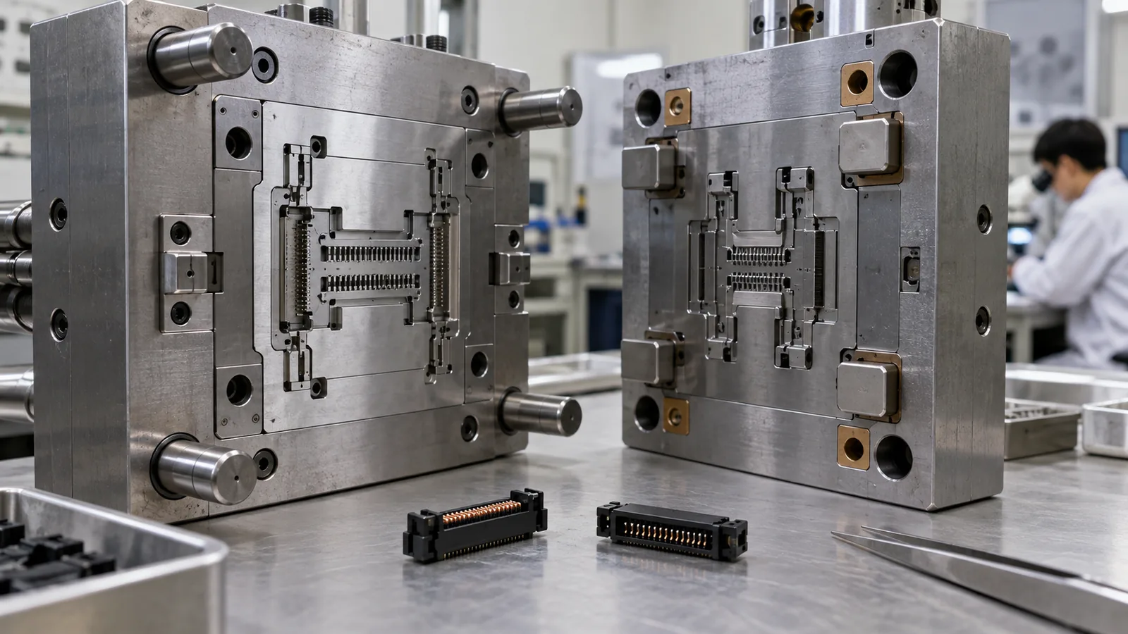
Contact windows, thin latches, and sealing faces offer little safe area for ejector load. Release should be directed through supported pads or broader nonfunctional surfaces. Draft and polish direction should reduce retention before more force is added.
The part must also remain oriented for terminal insertion or inspection. Static can cause small housings to cling to tooling or transfer equipment. A controlled pickup and nest may be more reliable than random drop collection, particularly when cavity identity must be retained.
Inspect ejection witnesses under the same magnification used for functional features. A small burr or indentation near a terminal path can interfere with insertion even if it is difficult to see unaided.
Inspect What the Assembly Actually Uses
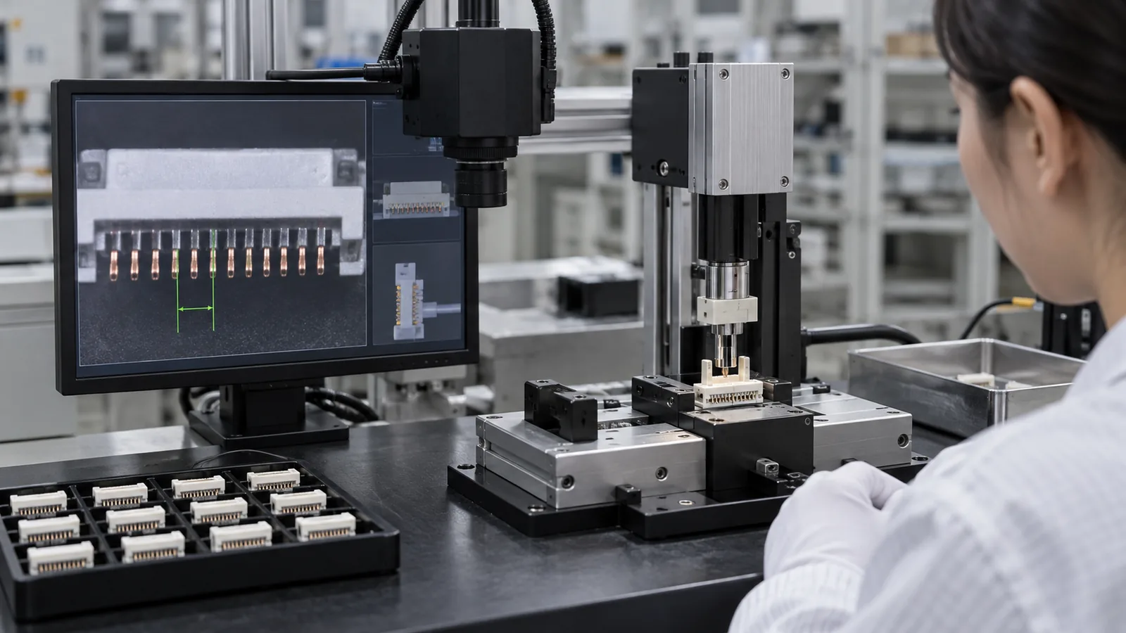
Optical measurement can capture pitch, window size, and profile, but the fixture and edge-detection rules must be repeatable. Gauge studies should use actual micro features, not only a convenient larger dimension.
- Measure cavity-specific molded geometry from functional datums.
- Verify terminal insertion depth and retention.
- Check mating force and positive latch engagement.
- Inspect seal compression or leak performance where applicable.
- Challenge temperature and conditioning expected in use.
- Link electrical or functional failures back to cavity and shot records.
The Micro Injection Molding process is valuable here because precise tooling, controlled delivery, handling, and feature-level metrology can be developed together. The acceptance plan should still end with the complete connector function.
Frequently Asked Questions

Why is connector pitch difficult to control?
Pitch reflects cavity accuracy, core alignment, directional shrinkage, warpage, ejection, conditioning, and measurement. It should be treated as a system result.
Can mold flow analysis eliminate weld lines?
It can help predict flow-front behavior and compare gates, but the final location and strength must be verified with the actual material and molded geometry.
Should terminals be included in early trials?
Yes, when terminal fit or retention governs function. Housing-only measurements can miss insertion damage and tolerance interactions.
What causes flash inside a terminal cavity?
Local shutoff clearance, insert alignment, wear, contamination, or excessive local pressure are common contributors. Location and cavity comparison help separate them.
Which data should a connector RFQ include?
Include mating datums, terminal drawings, functional forces, electrical and environmental requirements, material grade, critical dimensions, inspection method, and annual volume.