
Micro injection molding defects are easier to correct when the symptom is treated as evidence rather than as a reason to adjust every setting. A short shot near a micro rib, flash along a parting line, and a distorted feature after release point to different mechanisms. The fastest troubleshooting starts by locating when the defect is created: during filling, packing, cooling, ejection, handling, or measurement.
At micro scale, several causes can produce a similar-looking failure. Higher temperature may improve replication but can also widen the flash window. More pressure may increase part weight while compressing trapped gas or stressing a weak shutoff. This guide organizes defects by mechanism so changes can be tested one at a time.
Diagnostic route:
Read the Defect Location Before Changing Settings
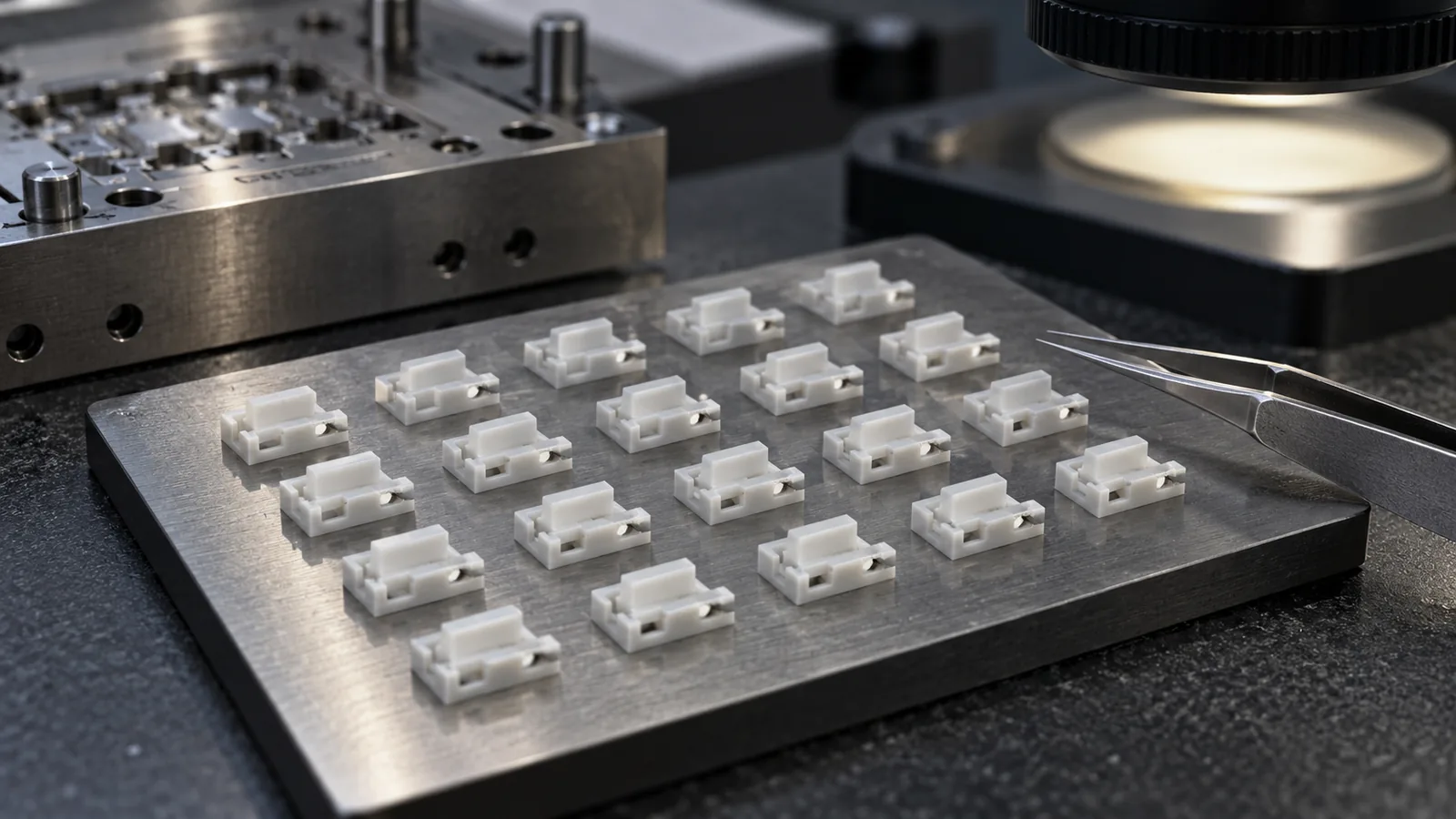
Location often carries more diagnostic value than severity. A repeated short shot at the end of a narrow flow path suggests premature freeze-off or trapped air. Random incomplete parts across different locations may indicate unstable material preparation, shot metering, or feed conditions. Flash concentrated around one shutoff points toward local tool fit, while flash around the complete parting line calls for a wider review of pressure, clamp support, contamination, and mold condition.
Orientation matters too. A distorted wall that follows the flow direction may reflect orientation and shrinkage. Damage concentrated around an ejector or deep core is more likely to occur after solidification. Before adjusting the process, mark the defect on the part drawing, identify the nearest gate and vent, and record whether the location changes between cavities.
Engineering judgment: if the failure remains in the same physical location while settings change, inspect the local mold and flow geometry before widening the process window.
Use a Symptom-to-Evidence Table
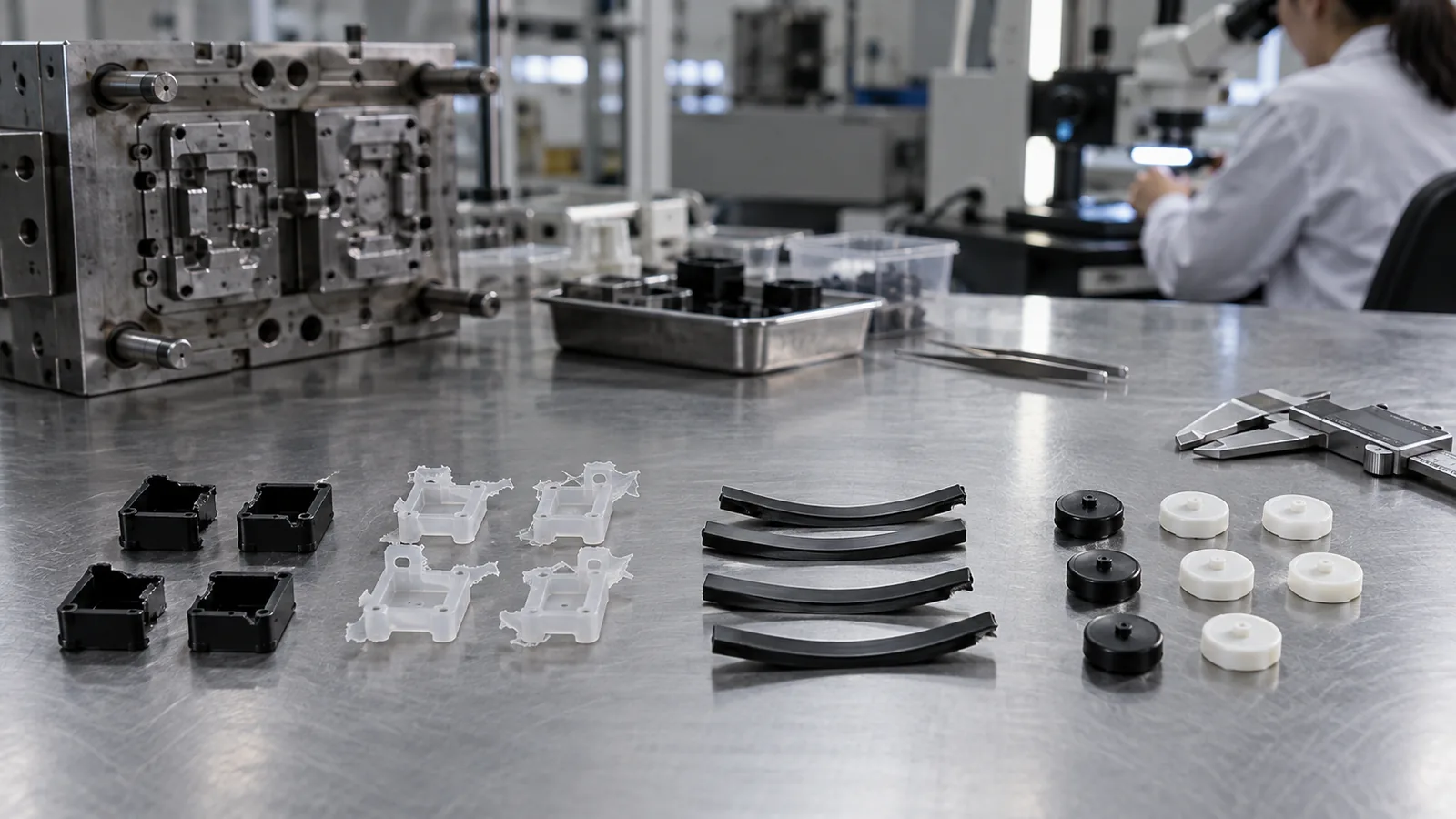
A defect name is only a starting point. The table below connects common symptoms with evidence that can confirm or weaken a hypothesis.
| Observed symptom | Likely mechanism | Evidence to check | First correction direction |
|---|---|---|---|
| Short shot | Freeze-off, trapped gas, or insufficient delivered melt | Last-fill location, vent condition, cavity pressure pattern | Restore the flow or air path before adding pressure |
| Micro flash | Local clearance, excessive cavity pressure, or contamination | Flash location, shutoff contact, cavity comparison | Confirm tool fit and pressure timing |
| Incomplete feature | Surface freeze or poor local replication | Feature profile by distance from the gate | Review mold temperature, speed, and venting together |
| Warped or bent part | Uneven shrinkage, early release, or ejection load | Cooling pattern, gate orientation, ejector marks | Separate cooling distortion from release damage |
| Weight variation | Metering, gate freeze, moisture, or feed instability | Shot sequence, cavity pressure, dryer and feed records | Stabilize material and delivery before tuning dimensions |
Flash and Short Shots Can Share a Root Cause
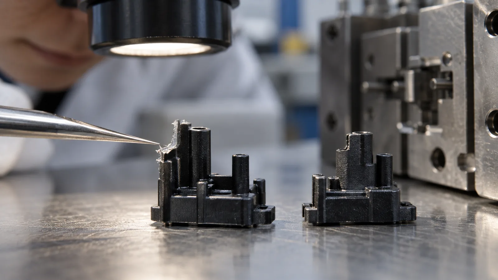
Flash and incomplete filling appear to be opposites, yet trapped gas can contribute to both. Compressed air can resist the advancing melt in one region while pressure finds a weaker parting-line clearance elsewhere. Raising injection pressure may reduce the visible short shot and simultaneously enlarge flash.
For flash, determine whether it is local or global. Local flash requires inspection of the shutoff, insert alignment, surface damage, and contamination. Global flash requires a broader review of cavity pressure, clamp support, viscosity, transfer position, and packing. The correction should address the mechanism that opens the leakage path, not merely trim the finished parts.
For a short shot, check whether the flow front stops at a thin transition, far-end pocket, or unvented feature. Material preparation and delivered shot consistency should be verified before increasing melt or mold temperature. A targeted mold flow analysis can help compare likely freeze-off and air-trap locations, followed by confirmation in the physical mold. A warmer process can improve filling, but it may also lengthen cooling, change shrinkage, and narrow the safe flash margin.
Incomplete Replication Is Not Always a Short Shot
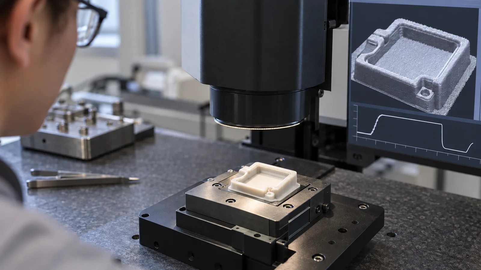
A component may look completely filled while its micro-feature profile remains incomplete. Feature replication depends on the local interaction between polymer flow, mold-surface temperature, pressure history, feature orientation, and distance from the gate. Checking only overall part weight or outer dimensions can miss this failure.
Measure the feature profile at defined locations instead of judging a single microscope image. Compare near-gate and far-gate features, flow-parallel and flow-transverse details, and multiple cavities. A change that improves one location but harms another indicates that the process window or feed layout needs further work.
Distortion must also be separated by timing. If the feature is correct while supported in the cavity but changes after release, demolding temperature, friction, draft, and ejection force become important. If it is already incorrect before release, filling, packing, cooling, or tool geometry is the stronger lead.
Change One Mechanism at a Time
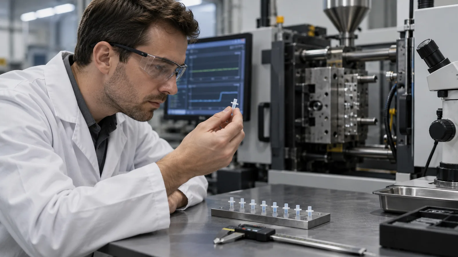
Random parameter changes make the process appear active while destroying the evidence needed to learn. A controlled trial starts with a stable baseline and a measurable response.
- Define the response. Use part weight, feature height, flash width, cavity pressure, or dimensional deviation—not “looks better.”
- Hold material preparation constant. Record resin lot, drying condition, feed condition, and elapsed residence time.
- Choose one hypothesis. For example, trapped gas at the final fill location.
- Change the smallest useful factor set. A vent-cleaning check may be more informative than altering five process settings.
- Compare by cavity and sequence. Separate a systematic effect from an isolated cavity problem.
- Confirm the result over repeated cycles. One acceptable part does not establish repeatability.
The broader Micro Injection Molding process connects precision tooling, controlled filling, handling, and metrology. Troubleshooting should follow the same chain instead of treating the molded part as the only evidence source.
Prevent Recurrence With a Control Plan
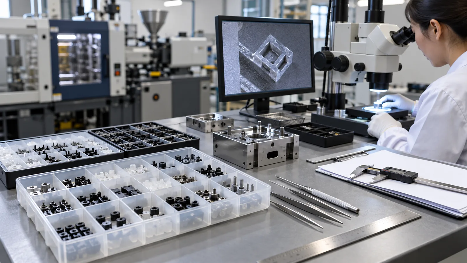
After a correction works, convert it into a control rather than leaving it as operator knowledge. Record the verified process window, vent-cleaning interval, critical tool surfaces, material preparation requirements, inspection locations, and reaction plan. Define which signal should stop production and which can trigger an adjustment within the approved window.
A useful control plan distinguishes product outputs from process signals. Part dimensions and feature profiles confirm what was produced; cavity pressure, temperature stability, material condition, and cycle events explain why. Both are needed when the acceptable range is narrow.
Tool maintenance should focus on the surfaces that govern the defect. Vent depth, shutoff contact, gate condition, ejector movement, insert alignment, and cavity cleanliness can drift at different rates. A custom mold making review can connect those features to replaceable inserts and steel-safe corrections. Linking maintenance records to defect maps makes recurrence easier to identify.
Inspection and reaction limits should also follow the site’s quality control workflow so cavity identity, measurement method, and corrective records remain connected.
Frequently Asked Questions

Why does adding pressure sometimes create more flash?
Higher cavity pressure can force melt into a local clearance at the parting line or shutoff. If trapped air or premature freeze-off caused the original filling problem, pressure may hide one symptom while creating another.
Can material drying affect micro-molding defects?
Yes. Moisture-sensitive polymers can show unstable viscosity, appearance problems, degradation, or reduced properties when preparation is inconsistent. Drying records should be checked before attributing every variation to the mold.
Is part weight enough to confirm a complete micro part?
No. Part weight is useful for process consistency, but it does not prove that every micro feature has the correct profile. Feature-level measurement is still required.
When should the mold be changed instead of the process?
Consider a tool correction when the defect remains at the same location across stable process trials, appears in one cavity only, or corresponds with a confirmed vent, gate, alignment, or shutoff limitation.
Should a defect-free sample be considered production-ready?
Only after the result repeats across enough cycles, cavities, material condition, and normal operating variation. A single good shot demonstrates possibility, not process capability.