
Good LSR Mold Design begins with a question that is easy to overlook: where will the liquid silicone be allowed to flow, and where must it be stopped? LSR has very low viscosity before cure, so small clearances, incomplete shutoffs, poor venting, or an unstable insert can become flash, air entrapment, or dimensional variation. The tool should be designed around the finished part’s function, not only around the fastest way to machine a cavity.
For projects that need Liquid Silicone Rubber (LSR) Molding, the most valuable design review happens before steel is cut. This guide uses a decision sequence: freeze functional surfaces, select the parting strategy, place gates and vents, manage shutoffs and inserts, and define the T1 learning plan.
Freeze functional surfaces before the parting line
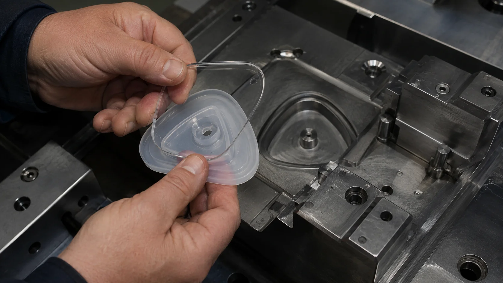
Mark every surface that seals, flexes, contacts a patient or fluid, locates another component, or remains visible. Then identify which surfaces can accept a gate or parting-line witness. A seal lip may need to stay on one mold half so its sealing edge does not carry a mismatch. A cosmetic grip may tolerate a witness mark on the back, while a transparent optical feature requires a carefully controlled cavity surface.
| Part feature | Tooling concern | Review question |
|---|---|---|
| Sealing lip | Mismatch and compression control | Can the seal land remain free of flash? |
| Thin membrane | Flow length and venting | Where will the last air leave? |
| Undercut | Release direction and tool motion | Can the part release without stretching? |
Choose a parting strategy the tool can hold
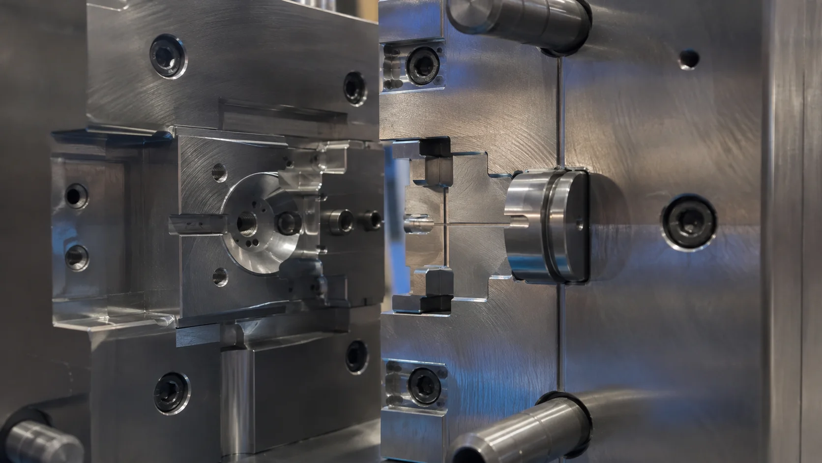
The parting line defines where the mold halves meet and where the tool must seal against incoming material. A long, interrupted, or stepped parting line increases the number of surfaces that must remain clean and aligned. If the line crosses a critical sealing or appearance area, change the orientation or redesign the interface before committing to steel.
Review shutoffs as a stack of physical conditions: steel contact, insert position, thermal expansion, clamp force, and maintenance access. A shutoff that works in a new tool can lose performance when residue builds on the land or an insert is not seated consistently. The facility and tooling environment must support the cleaning, measurement, and maintenance routine the design requires.
Place gates for flow, trimming, and function
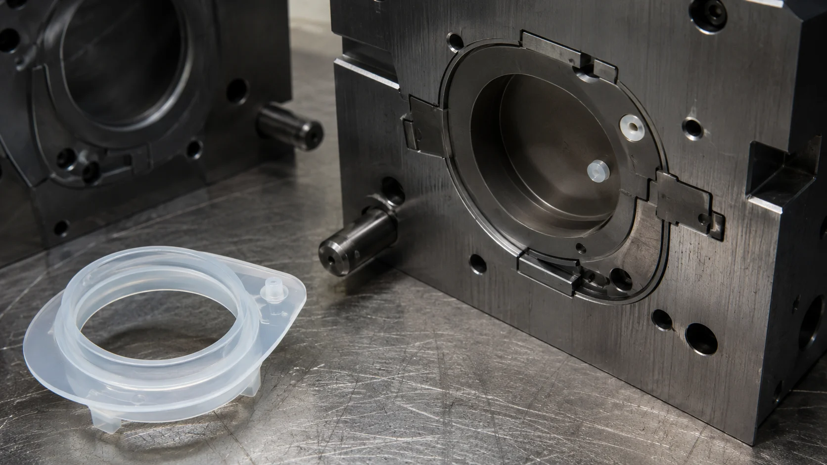
Gate location influences fill direction, weld-line position, venting demand, material waste, and secondary trimming. For a flexible part, do not create a hard spot at a bend or tear initiation point. For a sealing part, keep the gate away from a surface that must remain smooth. In a multi-cavity tool, balance flow length and resistance so one cavity does not become the process reference for all the others.
- Map the flow front: identify the last-fill regions and possible weld lines.
- Place vents: connect end-of-fill areas and trapped pockets to a controlled escape path.
- Plan trimming: confirm the gate can be removed without damaging the part.
- Protect maintenance: make gates, runners, and sealing lands accessible for cleaning.
Treat venting as a controlled feature
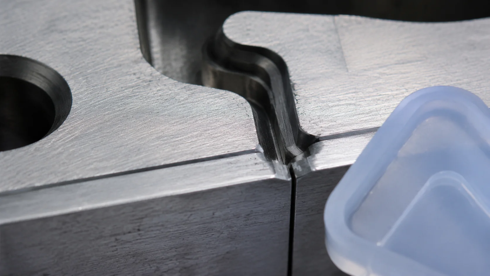
Vents must release displaced air without becoming a preferred escape route for liquid silicone. Location, land, depth, and connection to the outside of the tool should be reviewed together. A restrictive vent can leave bubbles or burn marks; an open vent can create flash. The correct balance depends on grade, flow path, cavity pressure, and cleaning practice.
Air can collect behind ribs, around pins, at a weld line, or inside an insert pocket. Do not assume one vent at the geometric end is enough. Use filling evidence to decide whether extra micro-vents, vacuum assistance, or a changed gate position is justified.
Design inserts and release features for repeatability
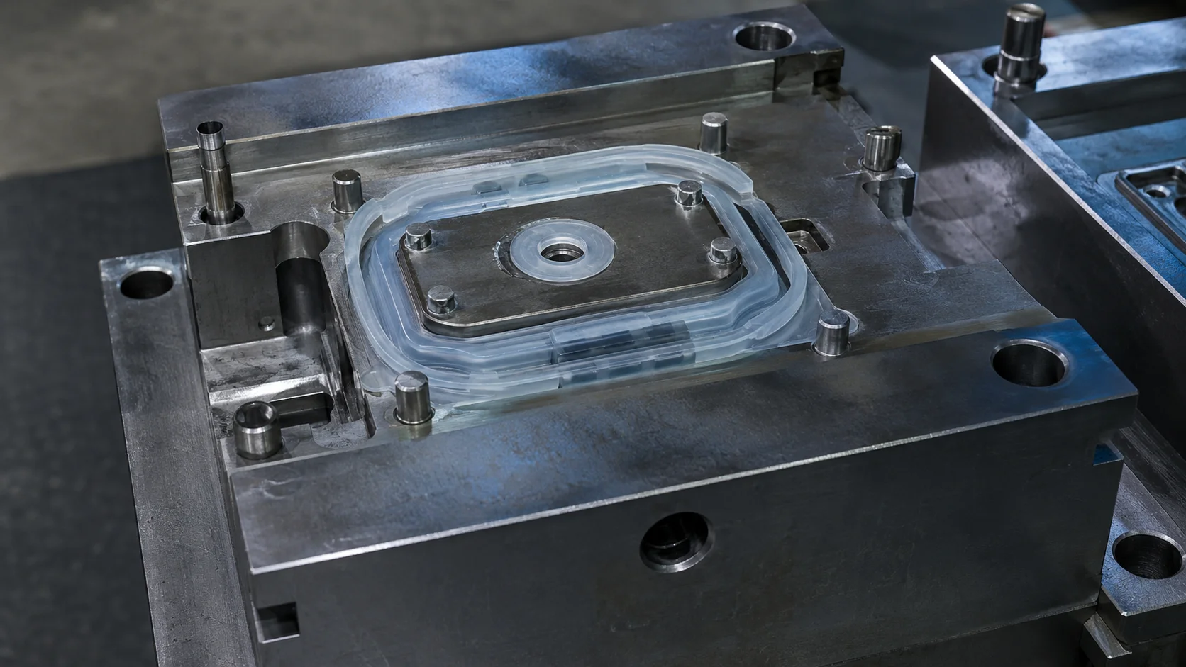
When LSR is molded around a rigid substrate, the insert must be located, supported, and protected from flash. A loose locator creates shift; an overly tight one can damage the substrate or prevent seating. Include a way to verify insert position before the mold closes, and keep the feature accessible for cleaning.
Flexible parts need a deliberate release path. Draft, radii, stripper features, air assistance, or controlled operator access may matter. Ejector pins are not automatically the best answer because a contaminant or mismatch around a pin can become a leak path. Review how the part will be handled after cure, not only how it leaves the cavity.
Use T1 to improve the design, not hide uncertainty
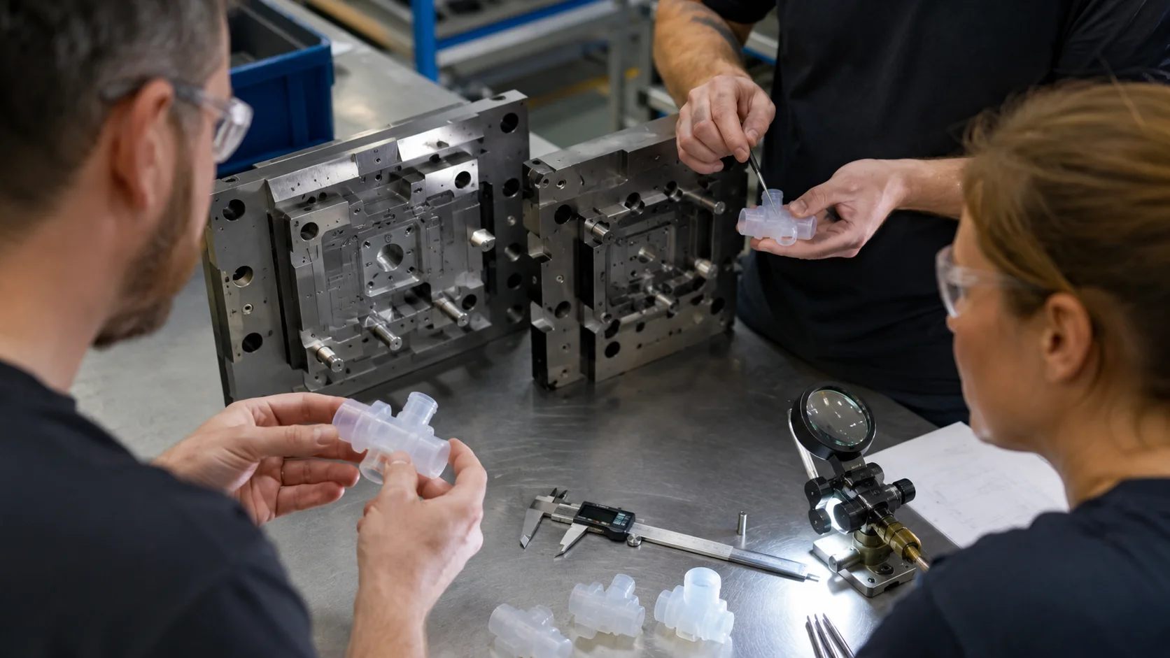
The first tooling trial should answer planned questions: Does the cavity fill in the expected order? Is air escaping where intended? Is flash concentrated in one shutoff? Does an insert remain centered? Can the part release without distortion? Record results by cavity and feature. “The mold needs tuning” is less useful than a map of flash, short fill, bubbles, and release marks.
A strong review package includes the CAD section, parting-line map, gate and vent rationale, critical tolerance callouts, insert-locating scheme, cleaning plan, and inspection method. The quality-control workflow helps connect tooling changes to measurable acceptance criteria. When flow, sealing, venting, and release are visible, the tool becomes easier to qualify and maintain.