
Where should the parting line go on a molded part? The answer is a design trade-off, not a cosmetic afterthought. Injection mold parting line placement affects which surfaces show a witness mark, how the tool opens around the geometry, where shutoffs and slides may be needed, and whether the part can be ejected without damaging a critical edge.
Choose the split only after identifying the part’s visible faces, functional datums, undercuts, and assembly interfaces. Moving a parting line can improve one surface while increasing tooling complexity or changing how flash is controlled elsewhere. The best location is the one the drawing, tool design, and inspection plan can all agree on.
Map the surfaces and tool-opening direction
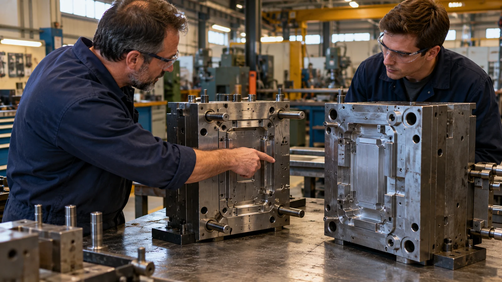
Start with the intended mold-opening direction and mark the surfaces that must remain free of a visible witness line. These may include a customer-facing panel, a sealing land, a sliding interface, or a dimensioning datum. Then identify where the tool can separate naturally without crossing a critical feature or trapping the part in the cavity.
Look at the full 3D shape rather than one favorable view. A split that appears straight in a side view may travel across a corner or curved surface elsewhere. If the geometry includes a hook, window, side port, or transverse hole, determine whether it can be formed with the primary opening direction or needs a core, slide, lifter, or a design change. The choice affects tool construction and maintenance as well as the line visible on the part.
Compare candidate locations by their consequences
There may be more than one workable split. Compare candidates using a short review rather than defaulting to the model’s largest edge. Involve the product designer and tool designer so appearance, function, and mold access are considered together.
| Candidate area | Potential advantage | Question to resolve |
|---|---|---|
| Natural perimeter edge | May keep the witness line away from a broad show surface | Does the perimeter provide a practical shutoff and ejection path? |
| Broad visible face | May simplify the tool split for some geometries | Can the visible witness mark be accepted, hidden, or moved? |
| Functional sealing or sliding region | Can align with a natural boundary in the part | Could mismatch, flash, or wear interfere with sealing or movement? |
| Complex contour or deep feature | May preserve a preferred cosmetic boundary | Would it add side actions, difficult shutoffs, or an inaccessible inspection area? |
This comparison does not assign a universal “best” side. The result depends on geometry, tool architecture, the acceptable witness-line location, and the drawing requirements. A focused 사출 금형 설계 review helps identify which consequences are real for the proposed tool rather than assumed from a 2D image.
Check shutoffs, draft, and ejection together
The parting line is also where opposing tool surfaces meet. A narrow shutoff, sharp transition, or long sealing edge can create a more demanding tool condition than a simple perimeter split. Review how the steel will support the shutoff, how the feature will be vented, and whether expected wear can be inspected and maintained.
Draft and ejection should be checked at the same time. A surface that looks acceptable when the part is stationary may resist release or drag across the tool during opening. Confirm that the selected split does not create a fragile edge, a difficult-to-eject undercut, or a mark on a surface that must remain cosmetic. These details belong in early 사출 성형 DFM 분석, before the team commits to a tool layout.
Do not use the parting line to conceal an unresolved flash concern. If flash or mismatch has already been observed, diagnose the actual tool and process condition separately; moving the nominal line on the drawing does not fix a damaged or poorly supported shutoff.
Make the decision clear on the drawing

Once the location is agreed, show the intended line and opening direction in a view that makes the route unambiguous. Call out any region where flash, mismatch, or a witness line is not acceptable, and identify the functional surfaces and datums that control assembly. Avoid relying on a note such as “parting line as required” when the line crosses a customer-visible or functional area.
At first trial, inspect the actual witness line, shutoff condition, part release, and critical dimensions against the agreed criteria. Include the approved split in the mold review record and drawing revision so later changes do not silently move it. Injection mold trial and validation is the point to verify that the proposed location works on molded parts, not just in CAD.
FAQ
Can a parting line be placed on a visible surface?
It can, if the product appearance criteria permit it and the line does not interfere with fit or function. Mark the acceptable area explicitly and confirm the molded result during the tool trial.
Does moving the parting line always make tooling more expensive?
No. It may simplify one feature and complicate another. The effect depends on the geometry, opening direction, shutoffs, and any side actions needed to release the part.
Is parting-line flash solved by changing its location?
Not necessarily. A line’s location is a design decision; flash is a molded-part symptom that can have multiple tool or process causes. Inspect the actual interface before changing the design.