
One gate can distort an entire optical path without leaving an obvious surface defect. Gate design for optical injection molding controls how the cavity fills, where orientation develops, how long packing pressure reaches the part, and where the gate vestige remains. A gate that produces a complete, glossy part can still create birefringence, focal shift or nonuniform transmission.
Decision rule: choose the gate by the optical failure it must avoid, then confirm that the same location can fill, pack, vent and be removed without damaging the functional surface.
이 글에서:
- Map the optical path first
- Predict orientation and weld lines
- Size for pressure transmission
- Compare gate concepts
- Prove the choice at trial
- 자주 묻는 질문
Draw the Optical Path Before Drawing the Runner
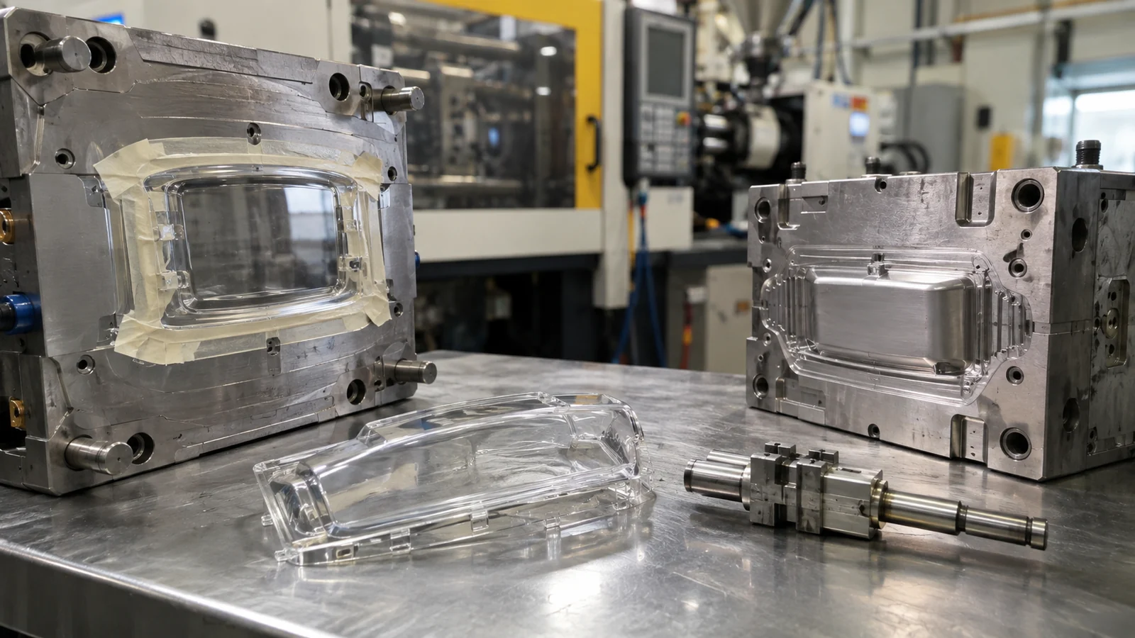
Mark the clear aperture, viewing face, light-entry and light-exit regions, reflective surfaces and mechanical datums. A gate hidden behind a bezel may still direct oriented flow across a lens. A gate outside the viewing area may be ideal cosmetically but unable to pack the thickest optical feature.
The map should also identify acceptable trimming access and vestige height. If a gate must be cut close to a polished edge, the trimming method can chip or stress the part. The mold, part handling and inspection teams need the same definition of the protected optical zone.
Flow Direction Becomes an Optical Variable
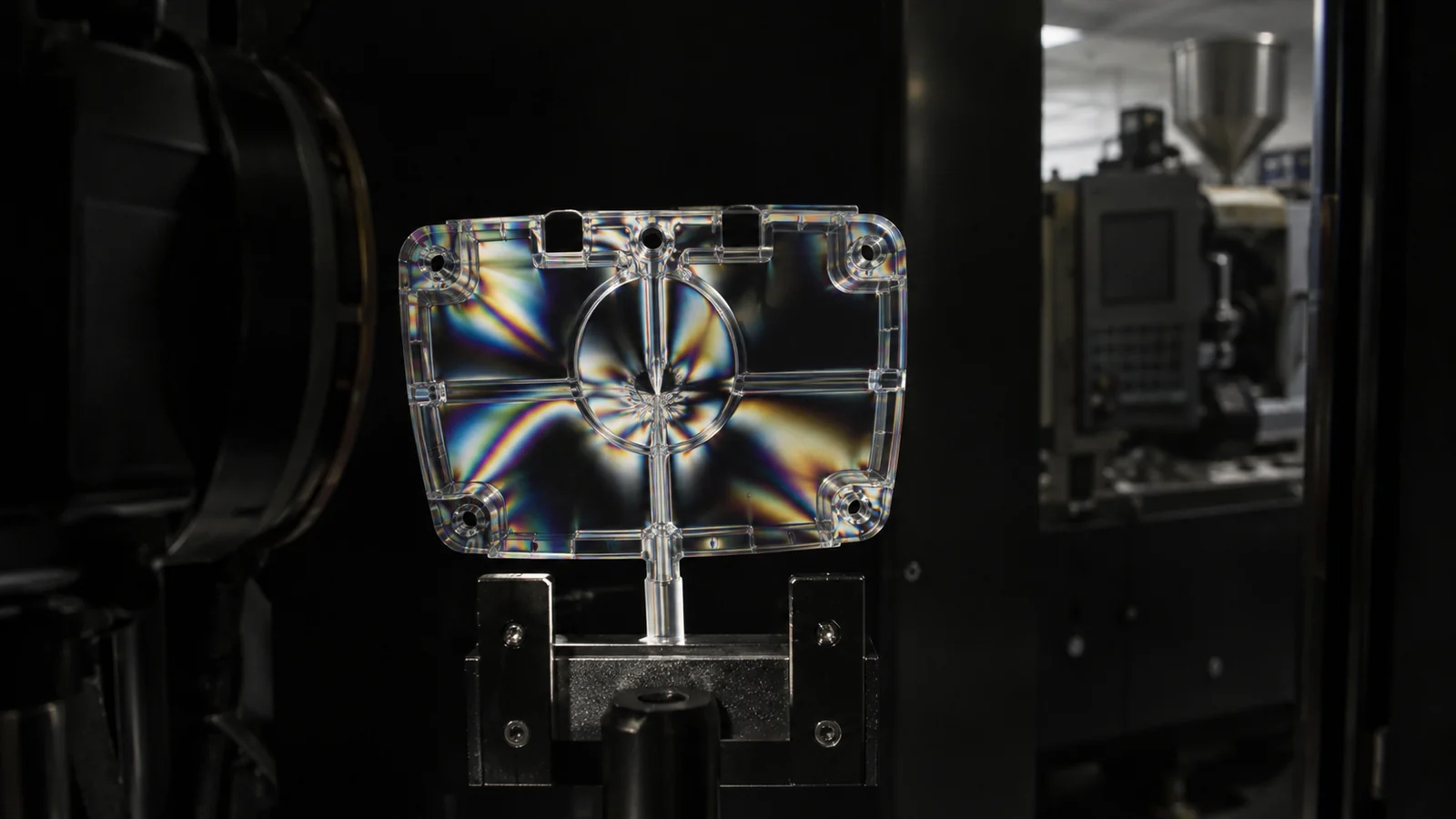
Polymer chains orient as melt accelerates through a restrictive gate and spreads through the cavity. Frozen orientation and uneven cooling can produce direction-dependent refractive behavior. The part may look transparent in normal light but show stress patterns between crossed polarizers or change the polarization state of transmitted light.
Multiple fronts create weld lines when they meet around holes, cores or opposing gates. In an opaque housing, a structurally acceptable weld line may be harmless. In an optical path, the same line can scatter light or interrupt an image. Place expected meeting lines outside the functional aperture whenever possible.
A Small Gate Is Not Automatically a Clean Gate
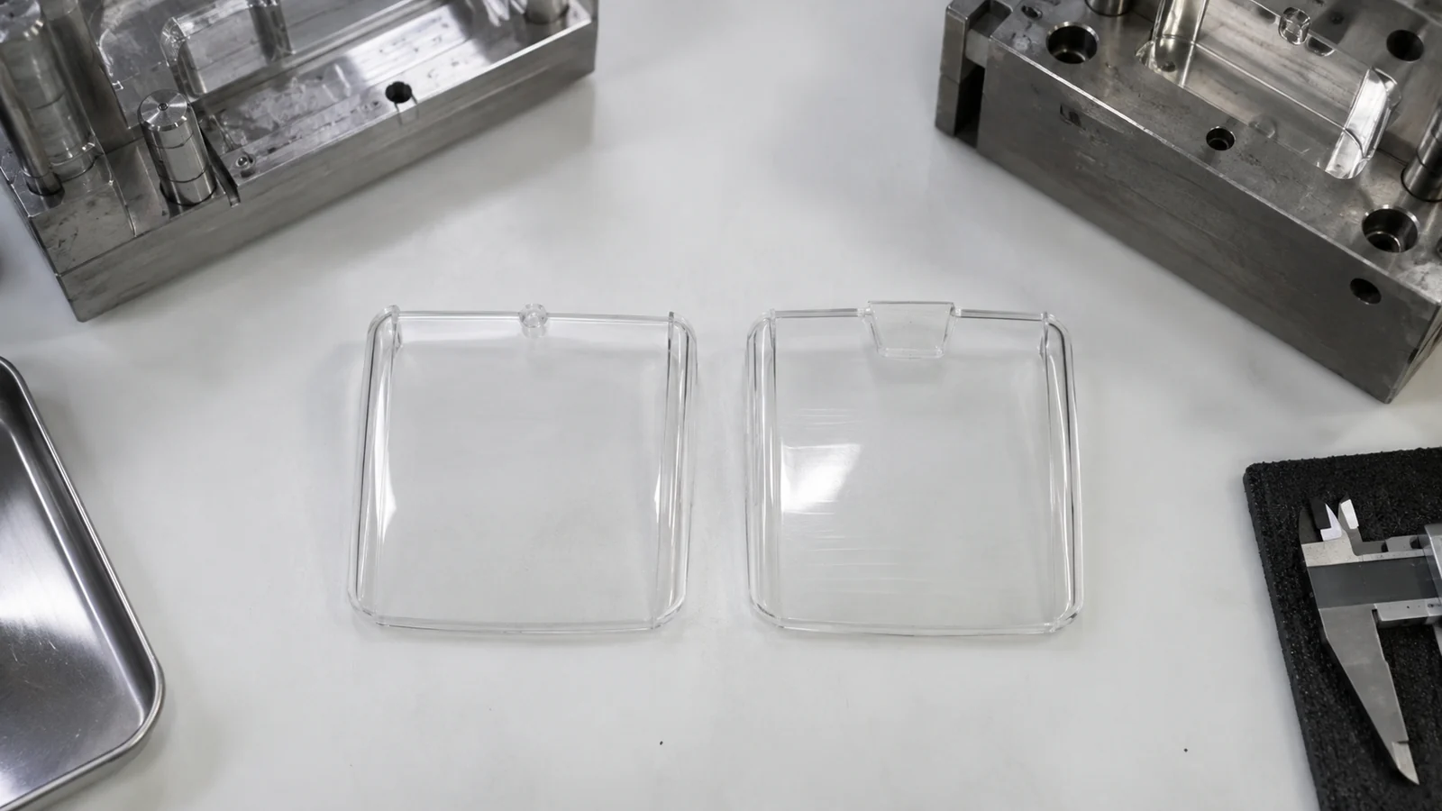
A small gate leaves less material to remove, but it raises shear and may freeze before a thick region is packed. A larger gate can reduce restriction and extend packing, yet leaves a larger vestige and can lengthen the time before safe removal. The correct size comes from the resin, local thickness, flow length, pressure requirement and optical consequence.
Use cavity-pressure or part-weight evidence to determine when the gate stops transmitting pressure. If additional hold time no longer changes weight, extending hold does not improve compensation. This distinction is central to 광학 및 투명 사출 성형, because overpacking can exchange sink for stress.
Compare Gate Concepts by Consequence, Not Habit
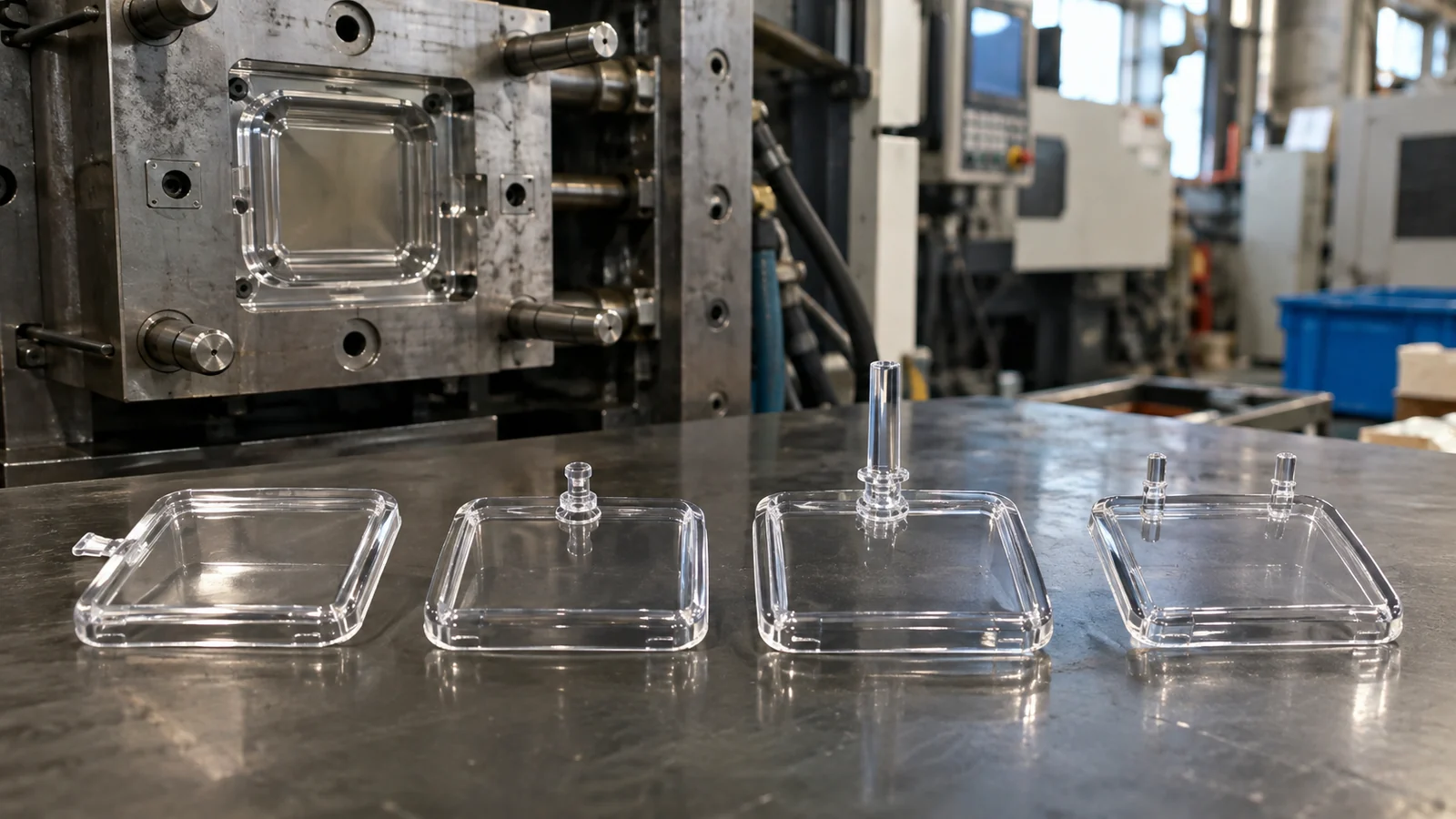
| Concept | Potential advantage | Optical concern |
|---|---|---|
| Edge or fan gate | Broad entry and controlled flow front | Trimming and edge stress |
| Pinpoint gate | Small vestige and automatic separation | High local shear and early freeze |
| Direct sprue | Strong packing path for heavy sections | Large central vestige and removal |
| Multiple gates | Shorter flow distance | Weld lines and balance sensitivity |
This table is a screening tool, not a universal ranking. The same gate type behaves differently with another resin, thickness or runner layout. Mold-flow analysis is useful for comparing fronts, pressure and temperature, but optical stress still needs physical verification.
Use a Trial Matrix That Can Disprove the Choice

Do not approve the gate because one setting produces one acceptable part. Run a bounded process window across realistic melt temperature, mold temperature, fill rate, transfer and packing conditions. Keep cavities separate and inspect the optical result after consistent conditioning.
Record gate vestige, part weight, fill pattern, weld-line location, polarized-light pattern and the product’s functional output. A robust gate maintains the acceptance criteria without a narrow, fragile combination of settings.
Include trimming and handling in the gate trial
A gate concept is incomplete until the part can be separated repeatedly. Hand cutting may make development samples look acceptable but hide labor, edge whitening and crack risk at production volume. Trial the intended degating fixture, robot or automatic break and inspect the edge after realistic handling.
For a supplier review, provide the protected optical area, allowable vestige, cosmetic viewing conditions, gate-prohibited surfaces, resin grade and functional optical test. If several gate locations are acceptable in CAD, keep that flexibility until the filling and stress evidence identifies the stronger option.
Watch the gate after the first approved run
Gate edges and hot-runner tips change through wear, deposits and maintenance. Trend vestige size, fill balance, cavity pressure or part weight so a gradual shift is caught before optical performance moves outside the limit. Keep startup parts separate until melt temperature and the runner system are stable.
For multi-cavity tooling, compare the same optical metric by cavity. A balanced runner at one condition may not remain balanced across the qualified window. Cavity-specific evidence also shows whether a failure belongs to the common process or one gate and insert.
자주 묻는 질문

Can a hot runner eliminate optical gate marks?
It can reduce cold-runner waste and change the vestige, but the melt still enters through a gate and can create local shear, heat and stress. Tip condition and temperature balance become additional controls.
Is the gate always placed in the thickest section?
That is a useful packing principle, not an absolute rule. Optical surfaces, weld lines, trimming and flow orientation may justify another location.
What should be reviewed before steel?
The optical-zone map, gate alternatives, fill and pack behavior, vent locations, trimming access, ejection, inspection method and acceptable process window.