
When a PEEK part fills on one cycle and changes appearance or dimensions after a stop, a barrel setpoint alone cannot explain the result. Follow the material through the whole thermal path. PEEK injection molding temperature is a coordinated thermal system, not a single machine setting. Drying temperature protects the material before processing; barrel and nozzle zones create a homogeneous melt; mold surface temperature controls flow, crystallization and dimensions; residence time determines whether the resin remains stable or degrades.
In this process guide:
- Define the four thermal controls
- Read molded-part evidence
- Balance crystallinity and cycle time
- Map cavity temperature
- Lock a production window
The setpoints must work as one system
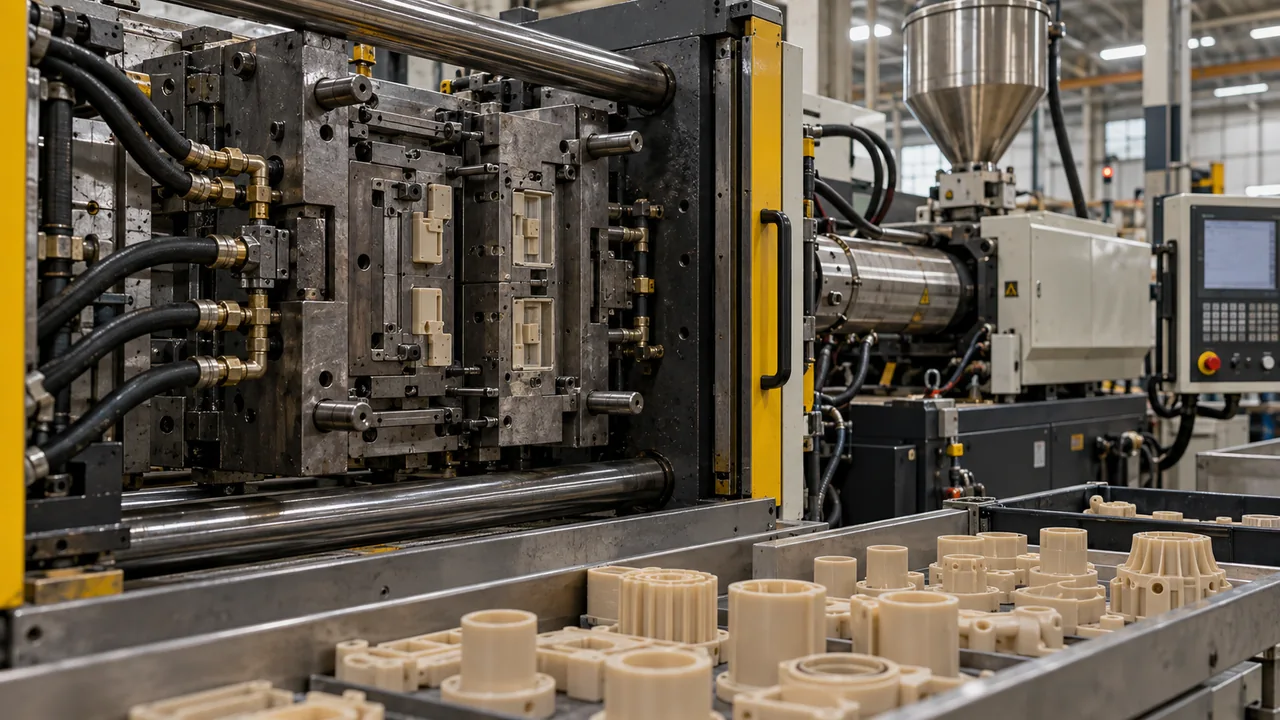
Supplier processing guides provide a starting window for the exact grade. Production development then adjusts within that window for shot size, residence time, flow length, wall thickness, gate design and heating capacity. Copying a temperature profile from another machine can fail because barrel geometry, shear history and actual mold-surface temperature differ. Drying, feed-zone control, barrel profile, nozzle, runner, cavity surface and cooling all contribute to the polymer history. A stable readout at one sensor cannot compensate for a cold gate or overheated dead spot. Map the complete path before changing individual setpoints. The resin supplier’s grade-specific processing recommendation is a starting point for setup, not a universal recipe for every PEEK component. Wall thickness, flow length, fillers, hot-runner design and cycle time change the required balance. Record actual material and tool conditions beside the machine recipe. If the same setting produces different results on two presses, investigate material residence and heat transfer before assuming the supplier’s recommendation is inconsistent. Controller values describe heater commands, while actual polymer and steel temperatures respond to shear, cycle time and sensor location. This gap explains why copied recipes behave differently across machines. Verify melt and cavity-surface conditions with appropriate measurement methods. Drying temperature controls preparation, barrel heat supports melting, nozzle conditions affect transfer, and the tool surface controls cooling and crystallization.
Four temperatures, four different jobs
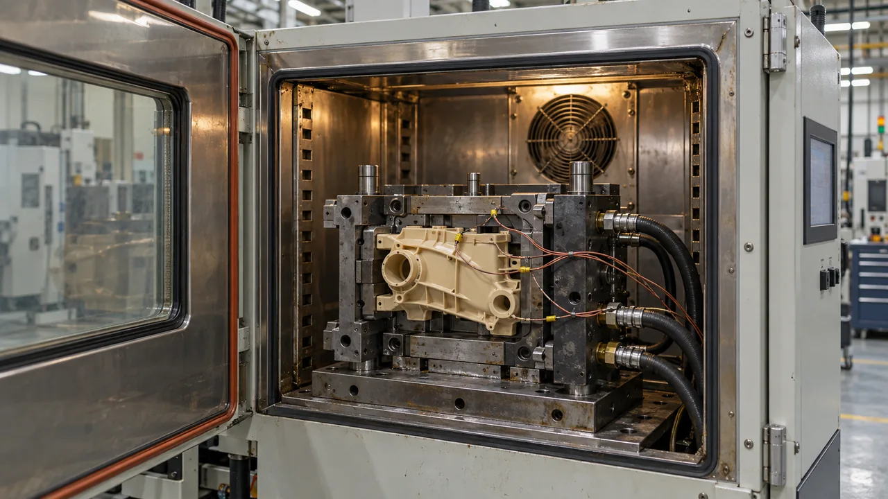
| Thermal control | Primary job | Evidence of error |
|---|---|---|
| Drying | Prepare resin and avoid moisture-related defects | Splay, bubbles or inconsistent quality |
| Barrel profile | Create a uniform melt without excessive thermal history | Unmelt, black specks, viscosity drift |
| Nozzle | Maintain flow into the sprue and gate | Freeze-off, drool or cold slug |
| Mold surface | Control filling, crystallization and dimensions | Warpage, unstable shrinkage, uneven color |
Measure the cavity, not only the controller
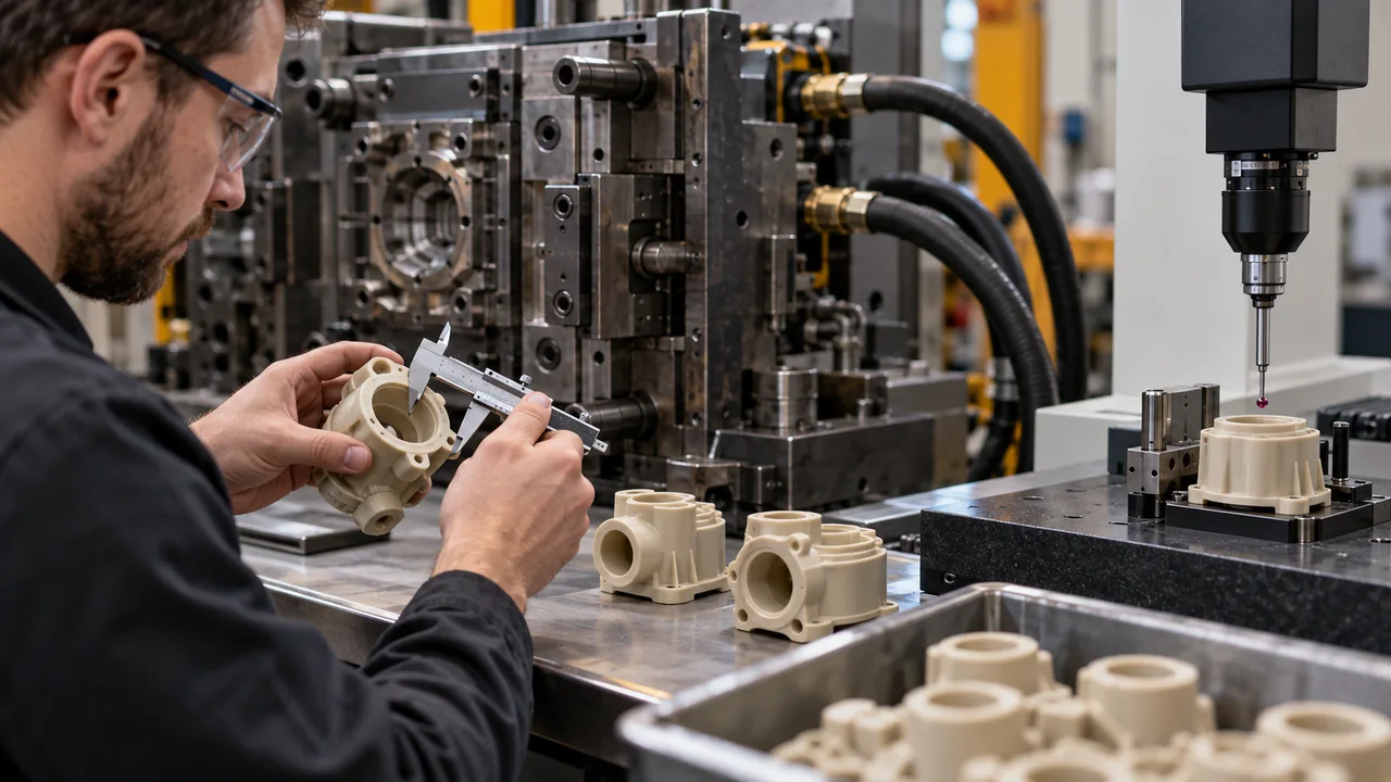
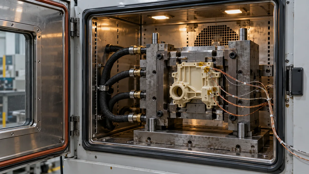
The temperature shown by an oil unit is not necessarily the temperature of every cavity surface. Hose loss, restricted circuits, insert thickness and heat transfer into the platen create local differences. Thin regions can freeze while a nearby heavy section remains hot. Treat these as linked variables with different jobs. A nozzle thermocouple may not reveal a dead spot; an oil-unit display may not represent a cavity edge. Confirm measurement location and instrument limits so the recorded value answers the engineering question. A precise-looking number can be misleading when it describes the wrong location. Slides, deep cores, inserts and thick mounting areas can remove heat faster than the surrounding cavity. Local cooling changes flow, weld-line quality and crystallinity even when average mold temperature is acceptable. Create a surface-temperature map after thermal equilibrium. Deep cores and moving inserts may receive heat through paths very different from the main cavity.
During validation, record cavity and core surface temperatures at repeatable points after the process reaches equilibrium. A thermal image or contact measurement can reveal imbalance that machine setpoints hide. During startup, they can lag behind the controller reading and produce changes in flow or dimensional stability. Map representative locations after equilibrium and after a planned interruption. Consider where sensors can remain repeatable and protected. The aim is to connect a local thermal difference with a particular part feature, rather than averaging away the coldest or hottest region.
Why mold temperature changes PEEK crystallinity
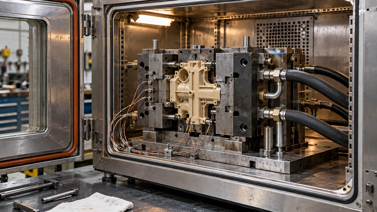
PEEK needs enough thermal opportunity to develop the intended semi-crystalline structure. An overly cold region can quench the polymer; an excessively hot or slow cycle can damage productivity and complicate ejection. Section thickness also changes cooling rate, so one setpoint may not produce one morphology throughout the part. Color or gloss changes can suggest different thermal history, but they do not quantify crystallinity or mechanical performance. A uniform-looking part may still contain regions with different shrinkage and durability. Link appearance to dimensions and, where necessary, laboratory analysis. Crystallinity influences shrinkage and material behavior, but it should not be optimized in isolation from the drawing and function.
This is why PEEK crystallization temperature belongs inside the same article and process study rather than on a separate page. The practical variable is the complete temperature-time history experienced by the molded section. Increasing tool heat changes cycle time, ejection condition and the thermal load on the surrounding equipment. Evaluate dimensions after the relevant conditioning period and compare function where necessary. If annealing is proposed, treat it as a separate controlled operation with its own dimensional assessment; it is not an automatic remedy for an unstable molding process.
Residence time can turn heat into degradation
A large barrel running a small shot keeps material hot for too long. Interruptions, slow recovery or repeated reprocessing add more thermal history. Symptoms may include dark contamination, odor, brittle parts or viscosity changes. Establish a shutdown and purge procedure before production begins. A small shot in a large barrel remains hot longer and may pass through repeated screw recovery cycles. Raising or lowering nominal temperature alone will not correct that mismatch. Calculate residence range for startup, normal running and interruptions. Residence time includes barrel, nozzle and any hot-runner volume, and it lengthens when production pauses. A safe steady-cycle setting may therefore become unsuitable during a long interruption. Match the machine and shot size, review dead spots, and use supplier-approved purge and shutdown procedures. Black specks or discoloration after restarting should prompt a history review before temperatures are reduced across the board, because colder processing can introduce filling problems without removing aged material.
How to establish a repeatable window
- Start from the exact grade supplier’s processing range.
- Confirm the machine can achieve and control the required temperatures.
- Map actual mold-surface temperatures.
- Run a structured study across fill, pack and cooling conditions.
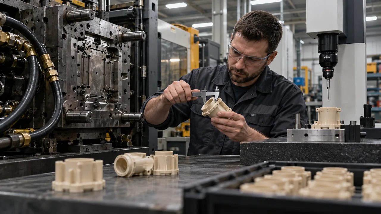
- Measure dimensions after a defined conditioning interval.
- Record alarm limits for melt behavior, residence time and mold balance.
当社の High-Temperature Polymer Molding approach connects this thermal study with tool heating, gate location and quality validation. Grade-specific requirements can be reviewed from the PEEK material portfolio. A process centered on one good setting may fail when normal variation affects moisture, cycle time or ambient conditions. The approved window should protect dimensions and performance at credible high and low limits. Run a structured window study and repeat after a planned stop. Define responses that reveal process quality: critical dimensions, part weight consistency, weld-line behavior, appearance and the relevant functional test. Vary parameters within a planned study, record interactions and wait for equilibrium before taking samples. A good center point proves only that one condition works. The approved window must also explain restart behavior and plausible variation in material preparation, with boundaries based on measured results rather than a copied temperature range.
よくある質問
Is a hotter PEEK mold always better?
No. The target is uniform, grade-appropriate crystallization and dimensional stability. Excess heat can extend cycles, change ejection behavior and exceed equipment limits. Higher tool heat also changes cycle time and ejection behavior. Use the selected grade recommendation and confirm the resulting dimensions and function rather than maximizing temperature as an isolated target.
Why does natural PEEK show uneven color?
Color variation can indicate differences in cooling or crystallinity, but contamination and degradation must also be ruled out. Confirm with process records and part testing. Compare the color pattern with local cavity temperatures, thickness and material residence history. Appearance is a diagnostic clue, not a quantitative measurement of crystallinity or proof of retained properties.
Can one temperature profile be used for every PEEK grade?
No. Viscosity, fillers, part geometry and supplier recommendations differ. Each grade needs its own validated process window. Fillers, flow characteristics and shot utilization affect the setup. Validate the selected grade on the intended tool and press, including restart behavior, before approving a shared recipe.